


© National Instruments Corporation vii GPIB-COM User Manual
Contents
Section One
Introduction
.......................................................................................................................... 1-1
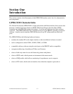
GPIB-COM Characteristics............................................................................................ 1-1
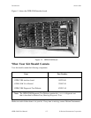
What Your Kit Should Contain ...................................................................................... 1-2
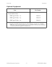
Optional Equipment........................................................................................................ 1-3
Section Two
Configuration and Installation
...................................................................................... 2-1
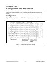
Configuration.................................................................................................................. 2-1
Switch and Jumper Settings................................................................................ 2-3
Base I/O Address and Interrupt Selection........................................................... 2-3
Talk/Listen Modes .............................................................................................. 2-4
Talk/Listen Address and Special Function Selection........................................... 2-5
Installation....................................................................................................................... 2-7
Special Considerations When Using the GPIB-COM.................................................... 2-8
Section Three
Function Description
........................................................................................................ 3-1
The GPIB-COM Interface .............................................................................................. 3-1
GPIB-COM Components............................................................................................... 3-3
Address Decoding .............................................................................................. 3-3
Configuration Jumpers ....................................................................................... 3-3
INS8250A Compatible Registers ....................................................................... 3-3
GPIB Acceptor and Source Handshaking........................................................... 3-3
Mode Control Logic............................................................................................ 3-3
Interrupt Control Logic ....................................................................................... 3-3
Direction Buffers ................................................................................................ 3-4
GPIB Transceivers.............................................................................................. 3-4
Section Four
Running Diagnostic Tests
............................................................................................... 4-1
The GPIB-COM Test Commands.................................................................................. 4-1
-1 printer test....................................................................................................... 4-1
-2 plotter test ....................................................................................................... 4-2
-c change COM configuration............................................................................. 4-3
-q quit.................................................................................................................. 4-3
Section Five
Programming the GPIB-COM
...................................................................................... 5-1
The GPIB-COM Registers ............................................................................................. 5-1
Transmitter Holding Register.............................................................................. 5-2
Receive Buffer Register ...................................................................................... 5-3
Divisor Latch Least Significant Byte (LSB) Register.......................................... 5-4
Divisor Latch Most Significant Byte (MSB) Register ........................................ 5-4
Interrupt Enable Register .................................................................................... 5-5
Interrupt Identification Register........................................................................... 5-7