


Programming the GPIB-COM Section Five
GPIB-COM User Manual 5-14 © National Instruments Corporation
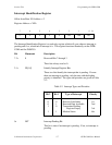
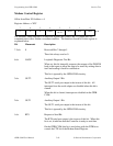
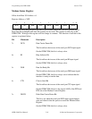
Modem Status Register
Offset from Base I/O Address = 6
Register Address = XFE
7 654 321
0
RI DSRDCD CTS DDCD TERI DDSR DCTS
R
The Modem Status Register gives the state of the modem control lines and tells whether any of
these lines have changed state since the register was last read. This register is read only on the
GPIB-COM. Writing to this register will not change its contents. The function of each bit in this
register is explained below.
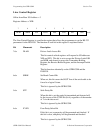
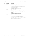
Bit Mnemonic Description
7r DCD Data Carrier Detect Bit
This bit reflects the inverse of the serial port DCD input signal.
On the GPIB-COM, this bit is always clear.
6r RI Ring Indicator Bit
This bit reflects the inverse of the serial port RI input signal.
On the GPIB-COM, this bit is always clear.
5r DSR Data Set Ready Bit
This bit reflects the inverse of the serial port DSR input signal.
On the GPIB-COM, this bit is always set to indicate that the
interface is ready to transfer data.
4r CTS Clear to Send Bit
This bit reflects the inverse of the serial port CTS input signal.
On the GPIB-COM, this bit is the logical AND of the DTR and
RTS bits of the Modem Control Register.
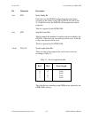
3r DDCD Delta Data Carrier Detect Bit
This bit is set when the serial port DCD input signal changes
state and cleared when the processor reads the Modem Status
Register.
On the GPIB-COM, this bit is always clear.