


Section Five Programming the GPIB-COM
© National Instruments Corporation 5-7 GPIB-COM User Manual
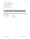
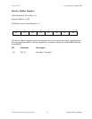
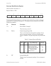
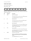
Interrupt Identification Register
Offset from Base I/O Address = 2
Register Address = XFA
7 654 321
0
00
0
0
0
ID1 ID0 INT
R
The Interrupt Identification Register is a read-only register which tells you when an interrupt is
pending and if so, what kind of interrupt it is. This register functions identically on the GPIB-
COM and the INS8250.
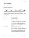
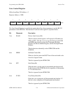
Bit Mnemonic Description
7-3r 0 Reserved Bits 7 through 3
These bits always read as 0.
2-1r ID[1-0] Identify Interrupt Register Bits
These two bits identify the interrupt that is pending. If more
than one interrupt is pending, only the one with the highest
priority is identified. The types and priorities are given in Table
5-2.
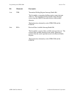
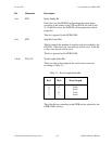
Table 5-2. Interrupt Types and Priorities
Bit 2 Bit 1 Type of Interrupt Priority
0 0 Receiver Line Status 1st
0 1 Received Data Available 2nd
1 0 Transmitter Holding
Register Empty 3rd
1 1 Modem Status 4th
0r INT Interrupt Pending Bit
This bit is clear if an interrupt is pending. If set, no interrupt is
pending.