


Appendix C Operation of the GPIB
© National Instruments Corporation C-3 GPIB-COM User Manual
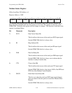
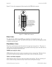
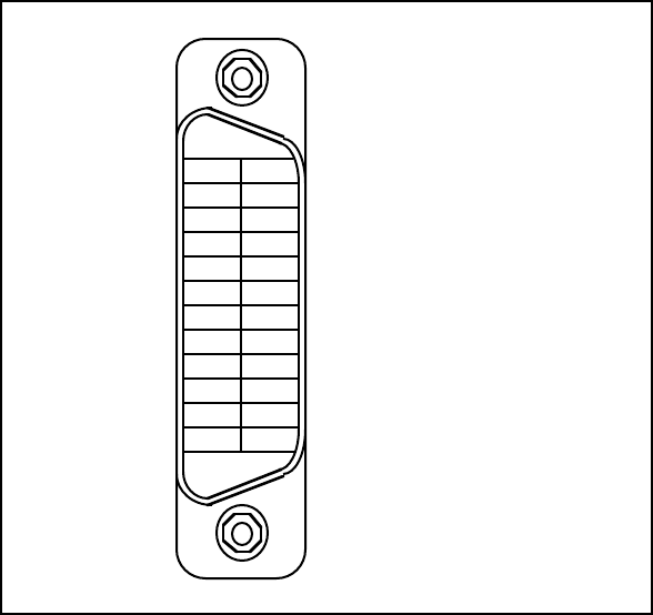
Figure C-1 shows the arrangement of these signals on the GPIB cable connector.
DIO1*
DIO2*
DIO3*
DIO4*
EOI*
DAV*
NRFD*
NDAC*
IFC*
SRQ*
ATN*
SHIELD
DIO5*
DIO6*
DIO7*
DIO8*
REN*
GND (TW PAIR W/DAV*)
GND (TW PAIR W/NRFD*)
GND (TW PAIR W/NDAC*)
GND (TW PAIR W/IFC*)
GND (TW PAIR W/SRQ*)
GND (TW PAIR W/ATN*)
SIGNAL GROUND
1
2
3
4
5
6
7
8
9
10
11
12
13
14
15
16
17
18
19
20
21
22
23
24
Figure C-1. GPIB Cable Connector
Data Lines
The eight data lines, DIO1 through DIO8, carry both data and command messages. All
commands and most data use the 7-bit ASCII or ISO code set, in which case the eighth bit, DIO8,
is unused or used for parity.
Handshake Lines
Three lines asynchronously control the transfer of message bytes among devices. The process is
called a three-wire interlocked handshake and it guarantees that message bytes on the data lines are
sent and received without transmission error.
NRFD (not ready for data)
NRFD indicates when a device is ready or not ready to receive a message byte. The line is driven
by all devices when receiving commands and by Listeners when receiving data messages.
NDAC (not data accepted)
NDAC indicates when a device has or has not accepted a message byte. The line is driven by all
devices when receiving commands and by Listeners when receiving data messages.