


Chapter 1 Introduction
VXI-MIO Series User Manual 1-6
National Instruments Corporation
Custom Cabling
Mating connectors and a backshell kit for making custom 96-pin cables
for your VXI-MIO Series module are available from National
Instruments.
If you want to develop your own cable, however, the following
guidelines may be useful:
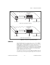
• For the analog input signals, shielded twisted-pair wires for each
signal yields the best results, assuming that you use differential
inputs. Tie the shield for each signal pair to the ground reference at
the source.
• You should route the analog lines separately from the digital lines.
• When using a cable shield, use separate shields for the analog and
digital halves of the cable. Failure to do so results in noise coupling
into the analog signals from transient digital signals.
Unpacking
Your VXI-MIO Series module is shipped in an antistatic package to
prevent electrostatic damage to the module. Electrostatic discharge can
damage several components on the module. To avoid such damage in
handling the module, take the following precautions:
• Ground yourself via a grounding strap or by holding a grounded
object.
• Touch the antistatic package to a metal part of your VXIbus chassis
before removing the module from the package.
• Remove the module from the package and inspect the module for
loose components or any other sign of damage. Notify National
Instruments if the module appears damaged in any way.
Do not
install a damaged module into your VXIbus chassis.
•
Never
touch the exposed pins of connectors.