


Chapter 4 Signal Connections
National Instruments Corporation 4-43 VXI-MIO Series User Manual
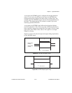
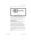
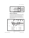
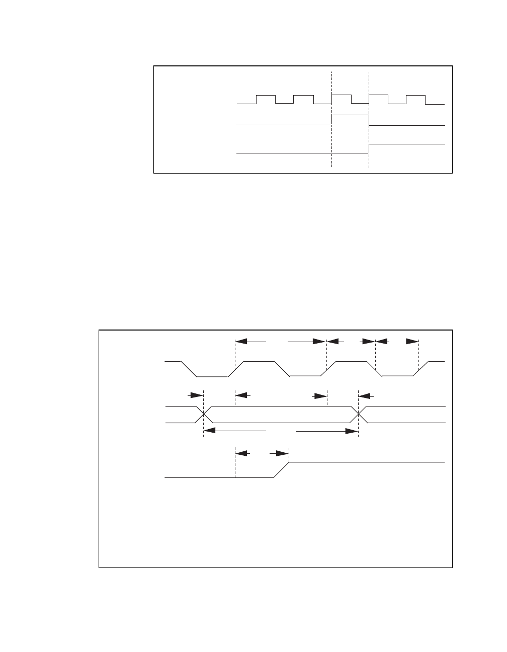
Figure 4-34.
GPCTR1_OUT Signal Timing
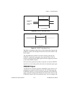
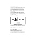
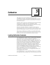
GPCTR1_UP_DOWN Signal
This signal can be externally input on the DIO7 pin and is not available
as an output on the I/O connector. General-purpose counter 1 counts
down when this pin is at a logic low and counts up at a logic high. This
input can be disabled so that software can control the up-down
functionality and leave the DIO7 pin free for general use. Figure 4-35
shows the timing requirements for the GATE and SOURCE input
signals and the timing specifications for the OUT output signals of your
VXI-MIO Series module.
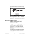
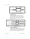
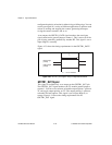
Figure 4-35.
GPCTR Timing Summary
GPCTR1_SOURCE
GPCTR1_OUT
GPCTR1_OUT
(Toggle output on TC)
(Pulse on TC)
TC
SOURCE
V
IH
V
IL
V
IH
V
IL
t
sc
t
sp
t
sp
t
gsu
t
gh
t
gw
GATE
t
out
OUT
V
OH
V
OL
sc
t
t
t
t
t
t 50 ns minimum
sp
23 ns minimum
gsu
10 ns minimum
gh
0 ns minimum
gw
10 ns minimum
out
80 ns maximum
Source Clock Period
Source Pulse Width
Gate Setup Time
Gate Hold Time
Gate Pulse Width
Output Delay Time