


Chapter 4 Signal Connections
National Instruments Corporation 4-9 VXI-MIO Series User Manual
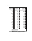
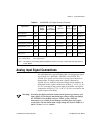
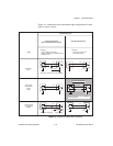
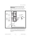
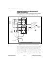
Analog Input Signal Connections
The VXI-MIO-64E-1 and VXI-MIO-64XE-10 analog input signals
are ACH<0..63>, AISENSE, AISENSE2, and AIGND. The
ACH<0..63> signals are tied to the 64 analog input channels of
both modules. In single-ended mode, signals connected to
ACH<0..63> are routed to the positive input of both modules. In
differential mode, signals connected to ACH<0..7, 16..23, 32..39,
48..55> are routed to the positive input of the PGIA, and signals
connected to ACH<8..15, 24..31, 40..47, 56..63> are routed to the
negative input of the PGIA.
Warning:
Exceeding the differential and common-mode input ranges distorts your
input signals. Exceeding the maximum input voltage rating can damage
the VXI-MIO Series module and your VXIbus system. National
Instruments is
NOT
liable for any damages resulting from such signal
connections. The maximum input voltage ratings are listed in Tables 4-1
and 4-2 in the
Protection
column.
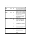
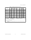
PFI5/UPDATE*
DIO — 5.5 V 3.5 at (4.6 V) 5 at 0.4 1.5 50 k
Ω
pu
PFI6/WFTRIG DIO — 5.5 V 3.5 at (4.6 V) 5 at 0.4 1.5 50 k
Ω
pu
PFI7/STARTSCAN DIO — 5.5 V 3.5 at (4.6 V) 5 at 0.4 1.5 50 k
Ω
pu
PFI8/GPCTR0_SOURCE DIO — 5.5 V 3.5 at (4.6 V) 5 at 0.4 1.5 50 k
Ω
pu
PFI9/GPCTR0_GATE DIO — 5.5 V 3.5 at (4.6 V) 5 at 0.4 1.5 50 k
Ω
pu
GPCTR0_OUT DO — — 3.5 at (4.6 V) 5 at 0.4 1.5 50 k
Ω
pu
FREQ_OUT DO — — 3.5 at (4.6 V) 5 at 0.4 1.5 50 k
Ω
pu
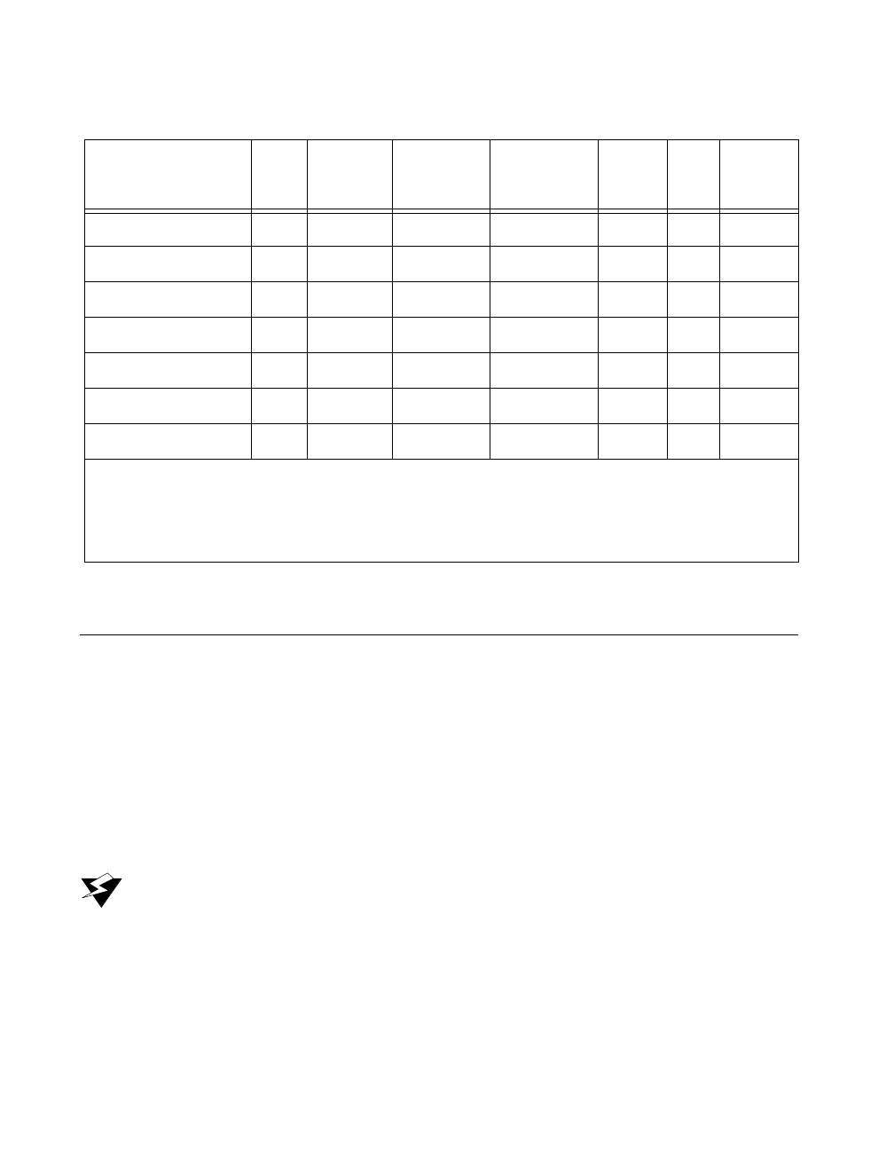
AI = Analog Input DIO = Digital Input/Output pu = pullup
AO = Analog Output DO = Digital Output
Note:
The tolerance on the 50 k
Ω
pullup and pulldown resistors is very large. Actual value may range between
17 and 100 k
Ω
.
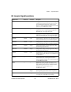
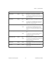
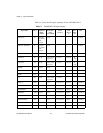
Table 4-2.
VXI-MIO-64XE-10 I/O Signal Summary (Continued)
Signal Name
Drive Impedance
Input/
Output
Protection
(Volts)
Power On/Off
Source
(mA at V)
Sink
(mA at V)
Rise
Time
(ns)
Bias