


Chapter 4 Signal Connections
VXI-MIO Series User Manual 4-8
National Instruments Corporation
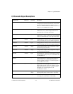
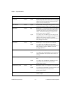
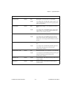
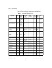
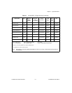
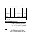
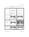
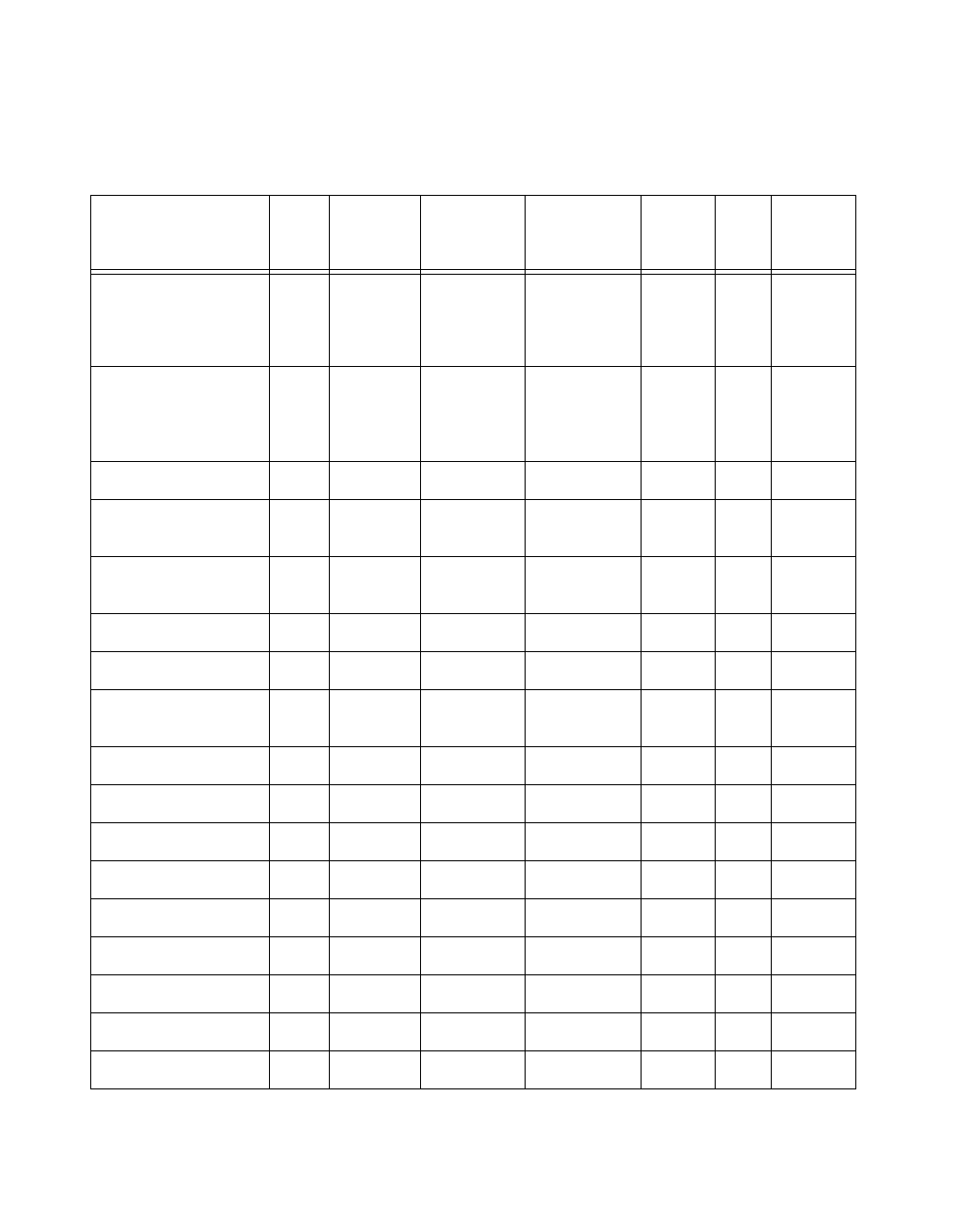
Table 4-2 shows the I/O signal summary for the VXI-MIO-64XE-10.
Table 4-2.
VXI-MIO-64XE-10 I/O Signal Summary
Signal Name
Drive Impedance
Input/
Output
Protection
(Volts)
Power On/Off
Source
(mA at V)
Sink
(mA at V)
Rise
Time
(ns)
Bias
ACH<0..63>
AI 100 G
Ω
in
parallel
with
100 pF
25/15 — — —
±
1 nA
AISENSE AI 100 G
Ω
in
parallel
with
100 pF
25/15 — — —
±
1 nA
AIGND AI — — — — — —
DAC0OUT AO 0.1
Ω
Short-circuit
to ground
5 at 10 V 5 at -10 V 5
V/
µ
s
—
DAC1OUT AO 0.1
Ω
Short-circuit
to ground
5 at 10 V 5 at -10 V 5
V/
µ
s
—
AOGND AO — — — — — —
DGND DO — — — — — —
+5 V DO 0.1
Ω
Short-circuit
to ground
1A — — —
DIO<0..7> DIO — 5.5 V 13 at (4.6 V) 24 at 0.4 1.1 50 k
Ω
pu
SCANCLK DO — — 3.5 at (4.6 V) 5 at 0.4 1.5 50 k
Ω
pu
EXTSTROBE* DO — — 3.5 at (4.6 V) 5 at 0.4 1.5 50 k
Ω
pu
PFI0/TRIG1 DIO — 5.5 V 3.5 at (4.6 V) 5 at 0.4 1.5 4.75 k
Ω
pu
PFI1/TRIG2 DIO — 5.5 V 3.5 at (4.6 V) 5 at 0.4 1.5 50 k
Ω
pu
PFI2/CONVERT* DIO — 5.5 V 3.5 at (4.6 V) 5 at 0.4 1.5 50 k
Ω
pu
PFI3/GPCTR1_SOURCE DIO — 5.5 V 3.5 at (4.6 V) 5 at 0.4 1.5 50 k
Ω
pu
PFI4/GPCTR1_GATE DIO — 5.5 V 3.5 at (4.6 V) 5 at 0.4 1.5 50 k
Ω
pu
GPCTR1_OUT DO — — 3.5 at (4.6 V) 5 at 0.4 1.5 50 k
Ω
pu