


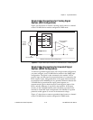
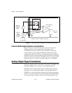
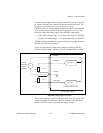
Chapter 4 Signal Connections
National Instruments Corporation 4-27 VXI-MIO Series User Manual
signal level. A 10 and 1.2
µ
s clock is available for generating a
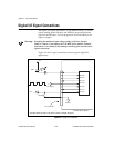
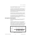
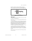
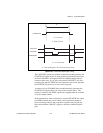
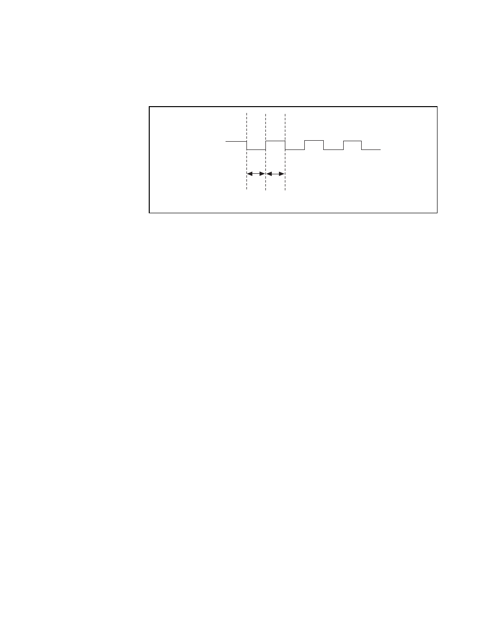
sequence of eight pulses in the hardware-strobe mode. Figure 4-14
shows the timing for the hardware-strobe mode EXTSTROBE* signal.
Figure 4-14.
EXTSTROBE* Signal Timing
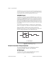
TRIG1 Signal
Any PFI pin can externally input the TRIG1 signal, which is available
as an output on the PFI0/TRIG1 pin.
Refer to Figures 4-11 and 4-12 for the relationship of TRIG1 to the data
acquisition sequence.
As an input, the TRIG1 signal is configured in the edge-detection mode.
You can select any PFI pin as the source for TRIG1 and configure the
polarity selection for either rising or falling edge. The selected edge of
the TRIG1 signal starts the data acquisition sequence for both
posttriggered and pretriggered acquisitions. The VXI-MIO-64E-1 and
VXI-MIO-64XE-10 support analog triggering on the PFI0/TRIG1 pin.
See Chapter 3 for more information on analog triggering.
As an output, the TRIG1 signal reflects the action that initiates a data
acquisition sequence. This is true even if the acquisition is being
externally triggered by another PFI. The output is an active high pulse
with a pulse width of 50 to 100 ns. This signal is set to input (High-Z)
at startup.
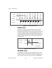
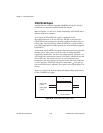
Figures 4-15 and 4-16
show the input and output timing requirements
for the TRIG1 signal.
t
w
t
w
V
OH
V
OL
t
w
= 600 ns or 5 µs