


National Instruments Corporation 4-1 VXI-MIO Series User Manual
Signal Connections
Chapter
4
This chapter describes how to make input and output signal connections
to your VXI-MIO Series module via the module I/O connector.
The VXI-MIO-64E-1 and VXI-MIO-64XE-10 I/O connector has
96 pins that you can connect to 68-pin accessories with the SH966868
shielded cable. Refer to Appendix B,
Optional Cable Connector
Descriptions
, for more information.
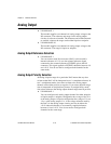
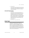
I/O Connector
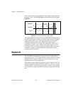
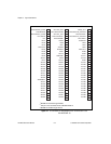
Figure 4-1 shows the 96-pin I/O connector pin assignments on the
VXI-MIO-64E-1 and VXI-MIO-64XE-10. A signal description follows
the connector pinouts.
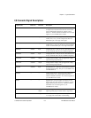
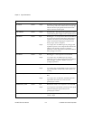
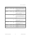
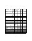
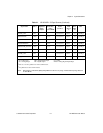
Warning:
Connections that exceed any of the maximum ratings of input or output
signals on the VXI-MIO Series modules can damage the module.
Maximum input ratings for each signal are given in Tables 4-1 and 4-2 in
the
Protection
column. National Instruments is
NOT
liable for any damages
resulting from signal connections that exceed these maximum ratings.