


National Instruments Corporation 2-1 VXI-MIO Series User Manual
Configuration and
Installation
Chapter
2
This chapter explains how to configure and install your
VXI-MIO Series module.
Module Configuration
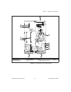
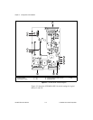
The VXI-MIO Series modules are software-configurable, except for the
VXIbus logical address. You must perform two types of configuration
on the VXI-MIO Series modules—bus-related configuration and data
acquisition-related configuration. Bus-related configuration includes
setting the VXIbus logical address, VXIbus address space (
A24
versus
A32
), VXIbus interrupt levels, and amount of VXIbus address space
required. Data acquisition-related configuration, explained in
Chapter 3,
Hardware Overview
, includes such settings as analog input
polarity and range, analog output reference source, and other settings.
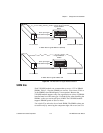
VXIbus Logical Address
Each module in a VXIbus system is assigned a unique number between
0 and 254. This 8-bit number, called the logical address, defines the
base address for the VXIbus configuration registers located on the
module. With unique logical addresses, each VXIbus module in the
system is assigned 64 bytes of configuration space in the upper 16 KB
of the A16 address space.
Logical address 0 is reserved for the Resource Manager in the VXIbus
system. Because the VXI-MIO Series modules cannot act as a Resource
Manager, do not configure the VXI-MIO Series modules with a logical
address of 0. The factory-default logical address for the
VXI-MIO-64E-1 is 3 and for the VXI-MIO-64XE-10 is 2.
Some VXIbus modules have dynamically configurable logical
addresses. These modules have an initial logical address of hex FF or
decimal 255, which indicates that they can be dynamically configured.