


Chapter 4 Signal Connections
National Instruments Corporation 4-25 VXI-MIO Series User Manual
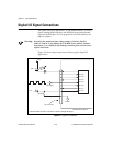
driver for the PFI2/CONVERT* pin. Be careful not to drive a PFI signal
externally when it is configured as an output.
As an input, you can individually configure each PFI for edge or level
detection and also for polarity selection. You can use the polarity
selection for any of the 13 timing signals, but the edge or level detection
will depend upon the particular timing signal being controlled. The
detection requirements for each timing signal are listed in the section
that discusses that individual signal.
In edge-detection mode, a minimum pulse width of 10 ns is required.
This applies for both rising-edge and falling-edge polarity settings.
There is no maximum pulse-width requirement in edge-detection mode.
In level-detection mode, there are no minimum or maximum
pulse-width requirements imposed by the PFIs themselves, but limits
may be imposed by the particular timing signal being controlled. These
requirements are listed later in this chapter.
Data Acquisition Timing Connections
The data acquisition timing signals are SCANCLK, EXTSTROBE*,
TRIG1, TRIG2, STARTSCAN, CONVERT*, AIGATE, and
SISOURCE.
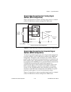
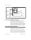
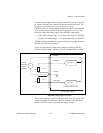
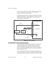
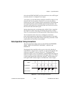
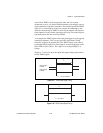
Posttriggered data acquisition allows you to view only data that is
acquired after a trigger event is received. A typical posttriggered data
acquisition sequence is shown in Figure 4-11. Pretriggered data
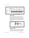
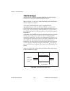
acquisition allows you to view data that is acquired before the trigger of
interest in addition to data acquired after the trigger. Figure 4-12 shows
a typical pretriggered data acquisition sequence. The description for
each signal shown in these figures is included later in this chapter.
Figure 4-11.
Typical Posttriggered Acquisition
13042
TRIG1
STARTSCAN
CONVERT*
Scan Counter