


Chapter 4 Signal Connections
National Instruments Corporation 4-19 VXI-MIO Series User Manual
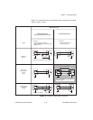
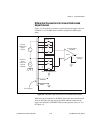
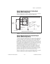
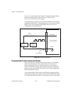
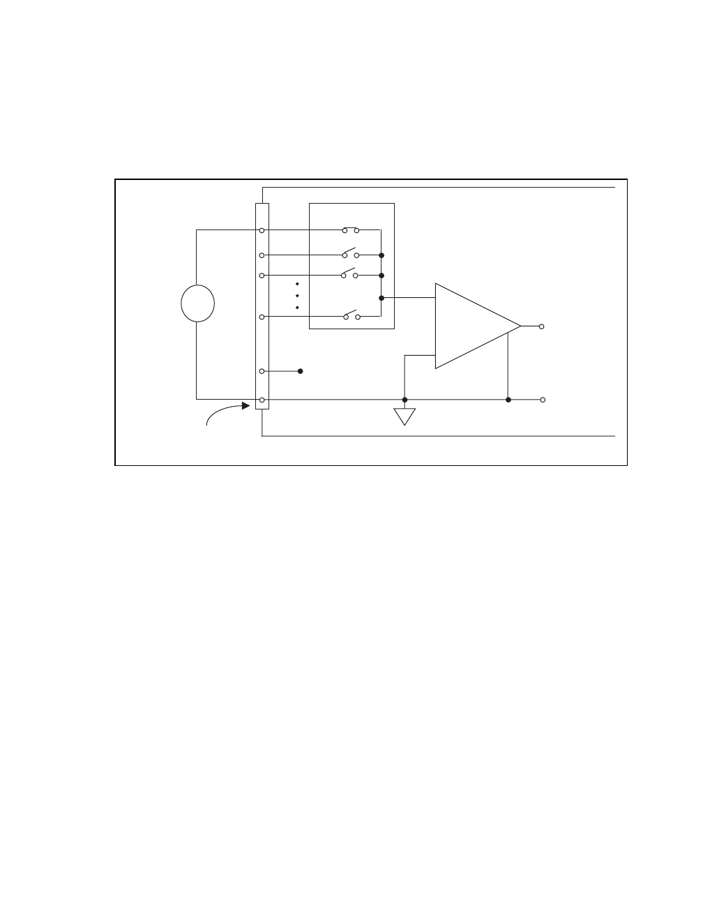
Single-Ended Connections for Floating Signal
Sources (RSE Configuration)
Figure 4-6 shows how to connect a floating signal source to a channel
on the VXI-MIO Series module configured for RSE mode.
Figure 4-6.
Single-Ended Input Connections for Nonreferenced or Floating Signals
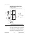
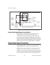
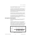
Single-Ended Connections for Grounded Signal
Sources (NRSE Configuration)
To measure a grounded signal source with a single-ended configuration,
you must configure your VXI-MIO Series module in the NRSE input
configuration. The signal is then connected to the module’s PGIA
positive input, and the signal local ground reference is connected to the
PGIA negative input. The ground point of the signal should, therefore,
be connected to the AISENSE pin. Any potential difference between the
VXI-MIO Series ground and the signal ground appears as a
common-mode signal at both the positive and negative inputs of the
PGIA, and this difference is rejected by the amplifier. If the input
circuitry of the VXI-MIO module were referenced to ground in this
situation as in the RSE input configuration, this difference in ground
potentials would appear as an error in the measured voltage.
Figure 4-7 shows how to connect a grounded signal source to a channel
on the VXI-MIO Series module configured for NRSE mode.
V
s
+
+
+
-
-
-
V
m
Measured
Voltage
Floating
Signal
Source
ACH<0..15>
AIGND
Instrumentation
Amplifier
I/O Connector
AISENSE
Selected Channel in RSE Configuration
PGIA
Other Input Multiplexers