


Chapter 2 Configuration and Installation
VXI-MIO Series User Manual 2-4
National Instruments Corporation
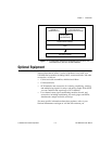
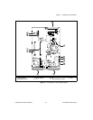
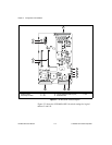
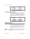
Figure 2-2.
VXI-MIO-64XE-10 Block Diagram
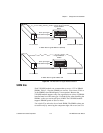
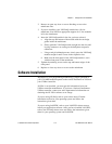
Figure 2-3 shows the VXI-MIO-64XE-10 switch settings for logical
address 2 and 192.
1 DRAM
2 Product Name
3 Assembly Number
4P3
5S1
6S2
7S3
8 Logical Address Switch (U73)
9 Serial Number
10 P1
11 P2
1
1
3
4
5
6
7
8
10 911
2