


Chapter 3 Hardware Overview
National Instruments Corporation 3-11 VXI-MIO Series User Manual
♦
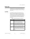
VXI-MIO-64XE-10
You can configure each analog output channel for either unipolar
or bipolar output. A unipolar configuration has a range of 0 to 10 V
at the analog output. A bipolar configuration has a range of -10 to
+10 V at the analog output. You do not need to configure both
channels for the same range.
Analog Output Reglitch Selection
♦
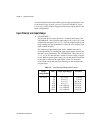
VXI-MIO-64E-1
In normal operation, a DAC output will glitch whenever it is
updated with a new value. The glitch energy differs from code to
code and appears as distortion in the frequency spectrum. Each
analog output of this module contains a reglitch circuit that
generates uniform glitch energy at every code rather than large
glitches at the major code transitions. This uniform glitch energy
appears as a multiple of the update rate in the frequency spectrum.
Notice that this reglitch circuit
does not
eliminate the glitches; it
only makes them more uniform in size. Reglitching is normally
disabled at startup and can be independently enabled for each
channel through software.
♦
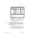
VXI-MIO-64XE-10
This module does not require reglitch selection.
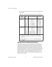
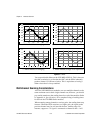
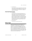
Analog Trigger
In addition to supporting internal software triggering and external
digital triggering to initiate a data acquisition sequence, the
VXI-MIO-64E-1 and VXI-MIO-64XE-10 also support analog
triggering. You can configure the analog trigger circuitry to accept
either a direct analog input from the PFI0/TRIG1 pin on the I/O
connector or a postgain signal from the output of the PGIA, as shown in
Figure 3-3. The trigger-level range for the direct analog channel is
±
10 V in 78 mV steps for the VXI-MIO-64E-1, and
±
10 V in 4.9 mV
steps for theVXI-MIO-64XE-10. The range for the post-PGIA trigger
selection is simply the full-scale range of the selected channel, and the
resolution is that range divided by 256 for the VXI-MIO-64E-1, and
divided by 4,096 for the VXI-MIO-64XE-10.