


Chapter 3 Hardware Overview
National Instruments Corporation 3-5 VXI-MIO Series User Manual
♦
VXI-MIO-64XE-10
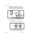
This module has two input polarities—unipolar and bipolar. The
VXI-MIO-64XE-10 has a unipolar input range of 10 V (0 to 10 V)
and a bipolar input range of 20 V (
±
10 V). You can program
polarity and range settings on a per channel basis so that you can
configure each input channel uniquely.
Note:
You can calibrate your VXI-MIO-64XE-10 analog input circuitry for
either a unipolar or bipolar polarity. If you mix unipolar and bipolar
channels in your scan list and you are using NI-DAQ, then NI-DAQ will
load the calibration constants appropriate to the polarity for which analog
input channel 0 is configured.
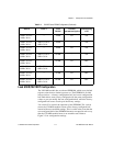
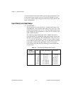
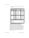
The software-programmable gain on this module increases its
overall flexibility by matching the input signal ranges to those that
the ADC can accommodate. The VXI-MIO-64XE-10 has gains of
1, 2, 5, 10, 20, 50, and 100. These gains are suited for a wide variety
of signal levels. With the proper gain setting, you can use the full
resolution of the ADC to measure the input signal. Table 3-3 shows
-5 to +5 V 0.5
1.0
2.0
5.0
10.0
20.0
50.0
100.0
-10 to +10 V
-5 to +5 V
-2.5 to +2.5 V
-1 to +1 V
-500 to +500 mV
-250 to +250 mV
-100 to +100 mV
-50 to +50 mV
4.88 mV
2.44 mV
1.22 mV
488.28
µ
V
244.14
µ
V
122.07
µ
V
48.83
µ
V
24.41
µ
V
1
The value of 1 LSB of the 12-bit ADC; that is, the voltage
increment corresponding to a change of one count in the ADC
12-bit count.
Note:
See Appendix A
, Specifications,
for absolute maximum
ratings
.
Table 3-2.
Actual Range and Measurement Precision (Continued)
Range
Configuration
Gain Actual Input Range Precision
1