


Chapter 4 Signal Connections
VXI-MIO Series User Manual 4-24
National Instruments Corporation
Connections
section later in this chapter. The general-purpose timing
signals are explained in the
General-Purpose Timing Signal
Connections
section later in this chapter.
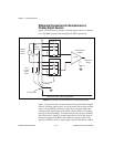
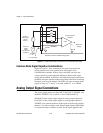
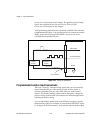
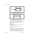
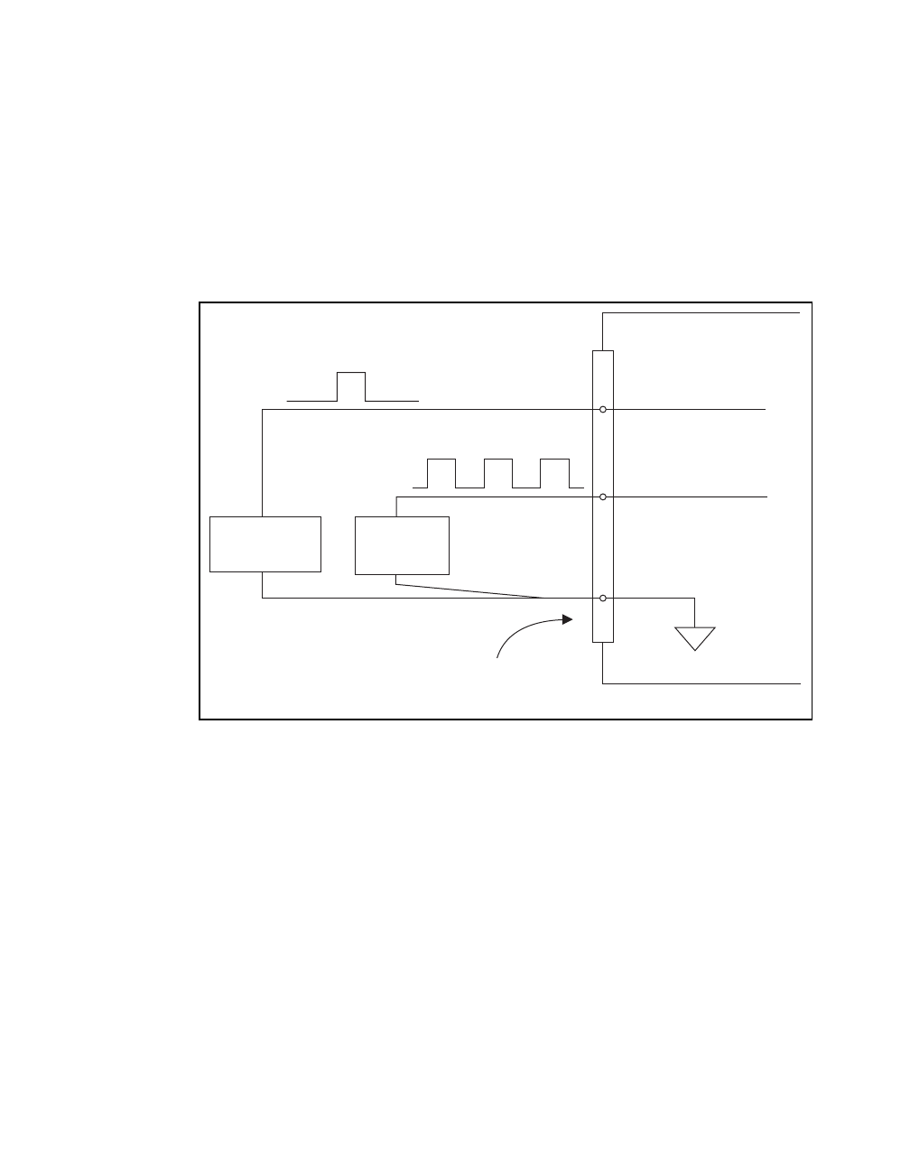
All digital timing connections are referenced to DGND. This reference
is demonstrated in Figure 4-10, which shows how to connect an external
TRIG1 source and an external CONVERT* source to two of the
VXI-MIO Series module PFI pins.
Figure 4-10.
Timing I/O Connections
Programmable Function Input Connections
There are a total of 13 internal timing signals that you can externally
control from the PFI pins. The source for each of these signals is
software-selectable from any of the PFIs when you want external
control. This flexible routing scheme reduces the need to change the
physical wiring to the module I/O connector for different applications
requiring alternative wiring.
You can individually enable each of the PFI pins to output a specific
internal timing signal. For example, if you need the CONVERT* signal
as an output on the I/O connector, your software can turn on the output
TRIG1
Source
DGND
PFI0/TRIG1
PFI2/CONVERT*
CONVERT*
Source
I/O Connector
VXI-MIO Series Board