


Page 2-2 NDA-24230 Issue 2.0
Chapter 2 VisuaLink 128/384 User Guide
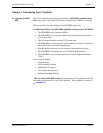
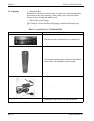
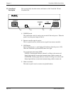
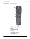
2.2 Front Panel
Description
This section briefly describes names and features of the VisuaLink 128 and
VisuaLink 384.
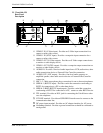
①
POWER
Switch
The push-button switch is used to turn on and off the main power. When the
power is on, the power lamp will be lit.
➁
Remote controller optical receiver
This is a optical receiver, which receives signal from remote controller.
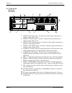
➂
LED Display
Power Lamp (power) : a green light will eluminate when the power is ON.
When the VisuaLink is powered OFF, there is no light.
Line connection status lamp (LINE)
LINE B1: Flashing light indicates channel is calling to the remote end.
Steady light indicates connection/communicating with the remote end.
LINE B2-B6: Flashing light indicates channel is calling to the remote end.
Steady light indicates connection/communicating with the remote end.
➃
Head set terminal
The head set jack is used to connect an optional headset.
POWER HEADSET
POWER
LINE
B1 B2-B6
①
➁
➂
➃