


Page 4-2 NDA-24230 Issue 2.0
Chapter 4 VisuaLink 128/384 User Guide
4.2 Hardware
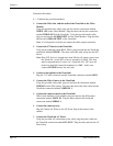
The preceeding sections will give step by step procedures for the installation of the
VisuaLink system in specific applications. Pick the application and follow the
instructions. This section gives a description on how to setup a VisuaLink as a
stand alone.
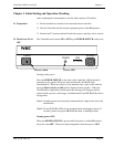
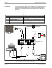
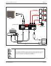
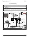
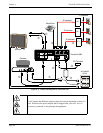
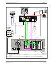
4.2.1 VisuaLink Standalone
Figure 4-1: Connection Diagram for VisuaLink 128
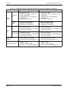
Parts List
No. Name Note
1 VisuaLink 128 or VisuaLink 384 CODEC Engine.
2 Controllable Camera Generic camera to allow for the transmission of video.
3 Microphone Generic microphone to allow for transmission of audio
4 Monitor TV monitor to display local and remote video
+
+
+
+
+
DC IN 5V
+
-
Serial1 Serial2/RMT
O
U
T
I
N
VIDEO2 VIDEO1 AUDIO
++
TEL S/T LINE
MIC1 MIC2 MIC3
➅
➆
➃
➂
①
➄
AC
VisuaLink 128
Camera
Monitor
➁
AC
Microphone
NT1
S Interface
U Interface