


NDA-24230 Issue 2.0 Page 4-11
VisuaLink 128/384 User Guide Chapter 4
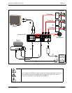
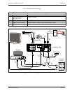
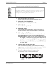
Connection Procedure for VisuaLink 128 and VisuaLink 384
1. Install the video capture card into the PC.
Procedure for installing video capture card are included with unit.
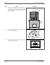
2. Position of the VisuaLink on desk top.
Place the VisuaLink on the desk top beside the PC.
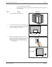
3. Position of the PC
Center the PC on the top of the table.
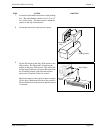
4. Position of the camera
Center the camera on top or next to the PC monitor. Using the two (2)
provided Velcro strips, attached the camera to the top of the PC monitor.
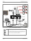
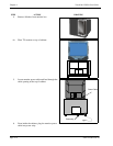
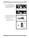
5. Position and connect the NT1 device
Position the NT1 to the left of the VisuaLink on the table top. Connect the
cable to the
NT1 S/T
interface and to the VisuaLink
ST/LINE
interface.
Note:
If the NT1 device is located more than 300 feet (91 meters) away from
the VisuaLink, it is best to use the 1 foot (0.3 meter) adapter cable and
set the NT1 to have a resistance of 100
Ω
. This step must be repeated
three (3) times for a VisuaLink 384. NT1 does not need to be installed
if network terminates in a PBX. In this case connect
ST/LINE
directly
into
WALL JACK
.
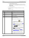
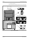
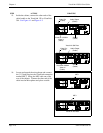
6. Connect the audio, video and control cables
Locate the cable bundle. The bundle should contain four (4) cables tie-
wrapped together. Each cable is labeled according to its connector. This label
identifies the cable connection to the proper equipment interfaces.
7. Connect the peripheral equipment to the power strip
The power strip is located on the floor behind the table.
An AC adapter has different output voltage and current depending on how it is
used. Please use the power adapter that is shipped with your unit. Also, if
incorrectly connected, it may damage the equipment.
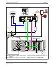
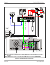
VIDEO
CAMERA
PC
VisuaLink NT1