


Page 4-4 NDA-24230 Issue 2.0
Chapter 4 VisuaLink 128/384 User Guide
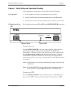
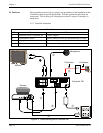
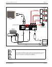
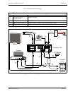
Connection Procedure
①
~
➆
indicate the procedure numbers.
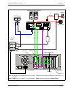
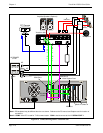
① Connect the Video Out and the audio of the VisuaLink to the Video
Monitor
Using the attached video cable, plug one side into the connection marked
VIDEO 1 IN
on the Video Monitor. Plug the other end into the connection
marked
VIDEO OUT
on the VisuaLink. Using the provided audio cable,
plug one end into the
AUDIO INPUT 1
of the Video Monitor. Plug the other
end into the
AUDIO OUTPUT
of the VisuaLink.
Note:
If a Voicepoint is used do not connect the audio output connection.
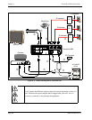
➁ Connect the NT1 device to the VisuaLink.
Using the provided data cable (RJ45 - RJ45), plug one end into the VisuaLink
connection labeled
ST/LINE
. The other end of the cable, plugs into the NT1
device.
Note:
If the NT1 device is located more than 300 feet (91 meters) away from
the VisuaLink, set the NT1 to have a resistance of 100
Ω
. This step
must be repeated three (3) times for a VisuaLink 384. NT1 does not
need to be installed if network terminates in a PBX. In this case
connect
ST/LINE
directly into wall jack.
➂ Connect a microphone to the VisuaLink.
Plug the 3 1/2 mini connector into the VisuaLink connection marked
MIC1
.
➃ Connect the Video Camera to the VisuaLink.
Using the provided video cable, plug one end into the connection marked
VIDEO IN
on the D30 camera. Plug the other end of the video cable into the
VisuaLink connection labeled
VIDEO IN 1
.
➄ Connect the camera control to the VisuaLink.
With a 8 pin minidin to 8 pin minidin, plug one end into the D30 camera
connection marked
VISCA IN
. Plug the other end into the VisuaLink
connection marked
SERIAL 1
.
➅ Connect the camera power.
Plug the Camera AC Power to the AC Power Strip at the bottom of the
cabinet.
➆ Connect the VisuaLink AC Power.
Using the provided AC transformer power cable, plug the power cable into
the VisuaLink connection marked
DC-IN-5V
. Plug the other end into the AC
Power Strip.