


Page 4-20 NDA-24230 Issue 2.0
Chapter 4 VisuaLink 128/384 User Guide
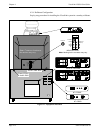
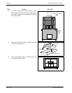
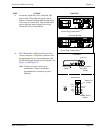
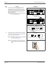
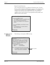
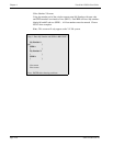
21. Locate the network cable (RJ45-RJ45) and
connect one end to the S/T LINE port of the
VisuaLink 128 or VisuaLink 384. Connect the
other end of the network cable into the S/T
interface of the NT1.
Note:
RJ45-RJ45 cable that is included with the
NT1 unit should be used.
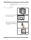
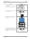
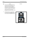
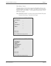
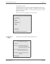
22. Connect the network cable from the U interface
on the NT1 to the network jack provided on the
room wall. Proceed to Step 24.
Note 1:
RJ45-RJ45 cable that is included with the
NT1 unit should be used.
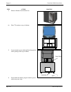
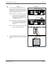
Note 2:
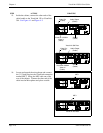
If connecting a VisuaLink 384 system,
Step 21 will have to be repeated three (3)
times.
STEP ACTION DRAWING
+
+
+ +
+
DC IN 5V
+
-
Serial1 Seri al2/RMT
O
U
T
I
N
VIDEO2 VIDEO1 AUDIO
++
TEL
S/T LINE
MIC1
MIC2
MIC3
RJ45 NT1 Cable
S/T
S/T
L-BK LINE PWR
DIN
INTERFACE
ST Interfaces
VisuaLink 128 Rear
NT1 Front
+
+
+
+
+
DC IN 5V
+
-
Serial1 Serial2/RMT
O
U
T
I
N
VIDEO2 VIDEO1 AUDIO
++
TEL S/T LINE 1 S/T LINE 2 S/T LINE 3
MIC1 MIC2 MIC3
VisuaLink 384 Rear
RJ45 NT1 Cable
1234
5
ON
POWER
U
NT1 Rear
U Interface