


NDA-24230 Issue 2.0 Page 4-21
VisuaLink 128/384 User Guide Chapter 4
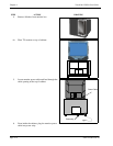
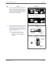
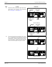
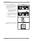
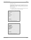
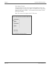
23. Locate the network cable (RJ45-RJ45) and
connect one end to the S/T LINE port of the
VisuaLink 128 or VisuaLink 384. Connect the
other end of the network cable into the network
interface provided in the room wall.
Note 1:
If the NT1 or network switch resides 300
feet (91 meters) or more away from the
VisuaLink 128 or VisuaLink 384, it is
recommended that the TERM switch is
set to
ON
on the VL128.
Note 2:
In the case a VL384 is being installed, the
network interface card must be taken out
of the system and the appropriate strap
must be set.
Note 3:
If the VL 384 is being installed, Step 23
must be repeated three (3) times.
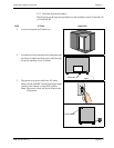
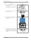
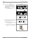
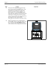
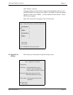
24. Locate the ON/OFF switch at the upper right
outside of the cabinet. Press the switch to the
ON
position.
STEP ACTION DRAWING
+
+
+ +
+
DC I N 5V
+
-
Serial1 Serial 2/RMT
O
U
T
I
N
VIDEO2 VIDEO1 AUDIO
++
TEL
S/T LINE
MIC1
MIC2
MIC3
RJ45 NT1 Cable
+
+
+
+
+
DC IN 5V
+
-
Serial1 Serial2/RMT
O
U
T
I
N
VIDEO2 VIDEO1 AUDIO
++
TEL S/T LINE 1 S/T LIN E 2 S/T LINE 3
MIC1 MIC2 MIC3
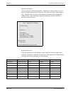
VisuaLink 384 Rear
RJ45 NT1 Cable
VisuaLink 128 Rear
ON/OFF Switch