


NDA-24230 Issue 2.0 Page 4-17
VisuaLink 128/384 User Guide Chapter 4
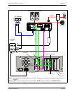
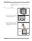
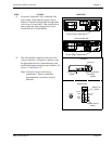
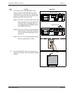
13. Locate the VisuaLink 128 or VisuaLink 384
power cable. Plug cable into power strip at
bottom of cabinet and feed cable through cable
slot in rear of second shelf. Plug second end of
power cable into power input at rear of the
VisuaLink 128 or VisuaLink384.
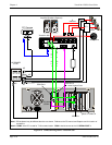
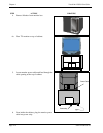
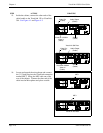
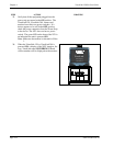
14. The cable bundle is labeled at the ends of the
various connectors. Plug these connectors into
the appropriate devices (camera/monitor) and
feed down through opening at top of cabinet. See
Figure 4-1 and Figure 4-2.
Note:
Connector layout could vary by
manufacture. Please consult their
documentation if connector layout is
different.
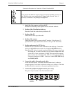
STEP ACTION DRAWING
Power Plug Connection
+
+
+
+
+
DC I N 5V
+
-
Serial1 Serial 2/RMT
O
U
T
I
N
VIDEO2 VIDEO1 AUDIO
+
+
TEL
S/T LINE
MIC1
MIC2
MIC3
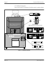
VisuaLink 128 Rear
+
+
+
+
+
DC IN 5V
+
-
Serial1 Serial2/RMT
O
U
T
I
N
VIDEO2 VIDEO1 AUDIO
+
+
TEL S/T LINE 1 S/T LINE 2 S/T LI NE 3
MIC1 MIC2 MIC3
VisuaLink 384 Rear
Power Plug Connection
VISCA In
12
VIDEO IN
S-VIDEO
VIDEO
AUDIO
L
MONO
R
AUDIO OUT
(VAR/FIX)
Camera Control
Sony D30
Camera Vout
CAMERA
MONITOR
VHF/UHF
Monitor Vin
Monitor Audio L
(Cable)
(Cable)
(Cable)
(Cable)