


Page 4-18 NDA-24230 Issue 2.0
Chapter 4 VisuaLink 128/384 User Guide
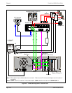
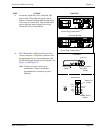
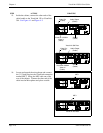
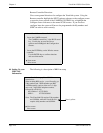
15. Inside the cabinet, connect the other ends of the
cable bundle to the VisuaLink 128 or VisuaLink
384. See Figure 4-1 and Figure 4-2.
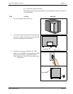
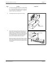
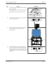
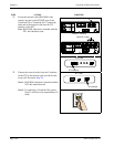
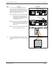
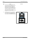
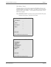
16. Locate and unpack the microphone and connect
the 3 1/2 inch plug into the VisuaLink connection
marked MIC1. String the MIC cable out of the
rear of the cabinet. Connect the other end of the
cable into the Microphone and place on table.
STEP ACTION DRAWING
+
+
+ +
+
DC I N 5V
+
-
Serial1 Serial 2/RMT
O
U
T
I
N
VIDEO2 VIDEO1 AUDIO
++
TEL
S/T LINE
MIC1
MIC2
MIC3
Serial 1
VisuaLink 128/384
(Cable)
Video In
(Cable)
VisuaLink 128 Rear
Video Out
(Cable)
Audio Output
(Cable)
+
+
+
+
+
DC IN 5V
+
-
Serial1 Serial2/RMT
O
U
T
I
N
VIDEO2 VIDEO1 AUDIO
+
+
TEL S/T LINE 1 S/T LINE 2 S/T LI NE 3
MIC1 MIC2 MIC3
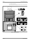
VisuaLink 384 Rear
Video Out
(Cable)
Audio Output
(Cable)
Serial 1
(Cable)
VisuaLink 128/384
Video In
(Cable)
+
+
+ +
+
DC I N 5V
+
-
Serial1 Serial 2/RMT
O
U
T
I
N
VIDEO2 VIDEO1 AUDIO
++
TEL
S/T LINE
MIC1
MIC2
MIC3
MIC1
+
+
+
+
+
DC IN 5V
+
-
Serial1 Serial2/RMT
O
U
T
I
N
VIDEO2 VIDEO1 AUDIO
++
TEL S/T LINE 1 S/T LINE 2 S/T LINE 3
MIC1 MIC2 MIC3
VisuaLink 384 Rear
VisuaLink 128 Rear
MIC1