


NDA-24230 Issue 2.0 Page 4-15
VisuaLink 128/384 User Guide Chapter 4
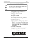
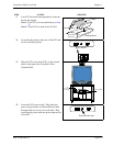
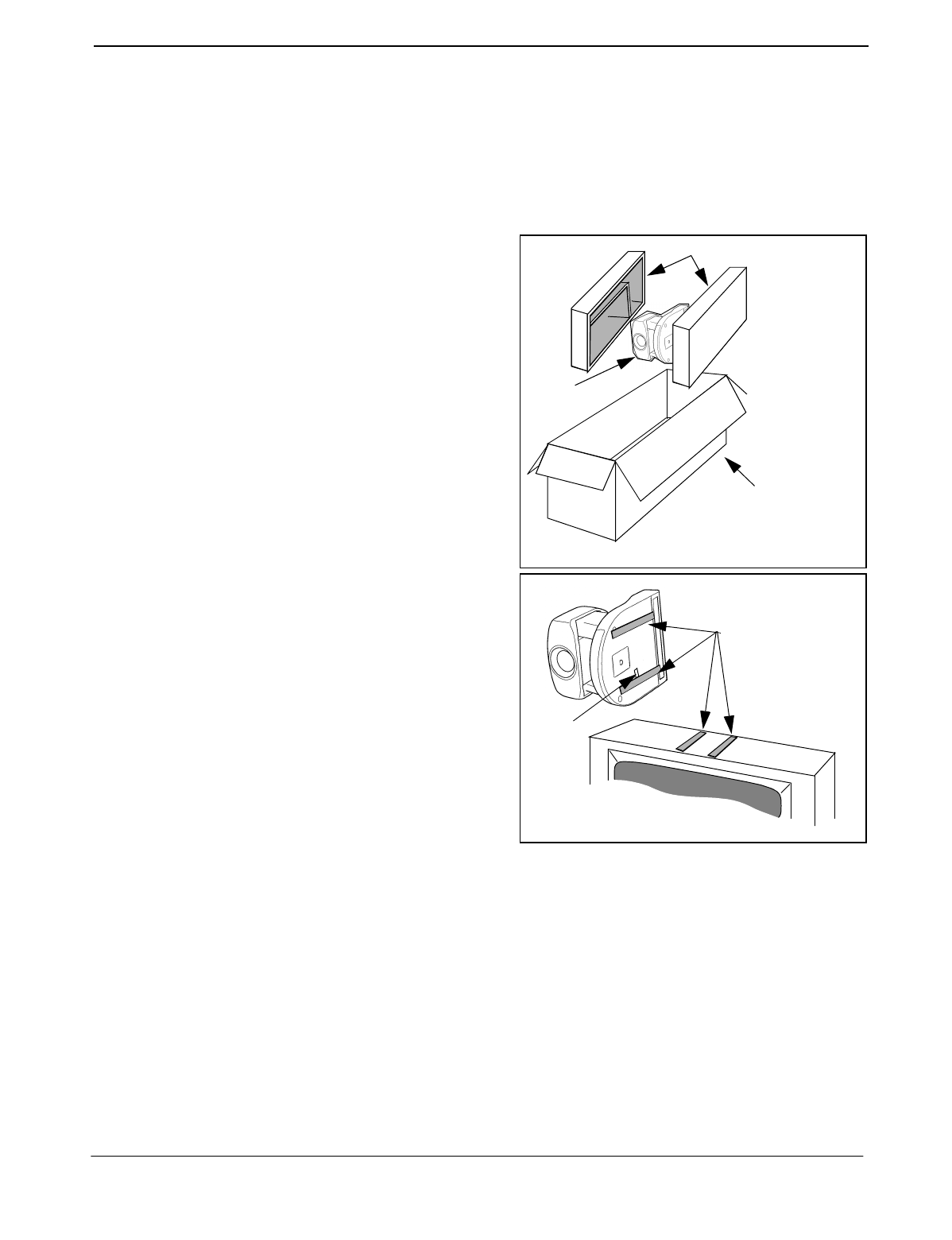
7. Locate the cable bundle and remove from packing
box. The cable bundle contains two (2) 5 in. (12
cm.) Velcro strips. Use these strips to mount the
camera to the top of the monitor.
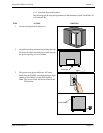
8. Locate the camera box and remove camera.
9.
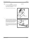
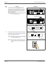
Set the IR switch on the Sony D30 camera to the
ON position. The IR switch is located on the
bottom of the Sony D30 camera. This will allow
for the Sony Camera to receive the IR codes from
the VisuaLink remote controller and transmit
them to the VisuaLink Codec for control.
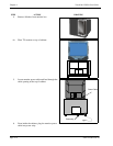
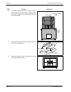
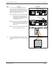
Mount the camera on the top of monitor, using the
Velcro strips. Make sure the front of the camera is
flush with the front of the monitor and the camera
is centered.
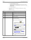
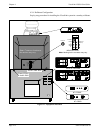
STEP ACTION DRAWING
Foam Inserts
Polyethylene
Bag
Packing Carton
Velcro Strips
IR OUT
Switch