


NDA-24230 Issue 2.0 Page 4-19
VisuaLink 128/384 User Guide Chapter 4
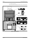
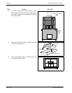
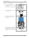
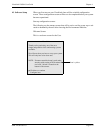
17. If an NT1 device has been purchased, locate the
device and unpack.
Note 1:
If an NT1 was not purchased go to Step
23.
Note 2:
Three NT1 are used for the VL384.
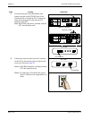
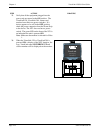
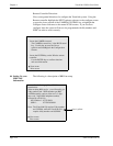
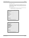
18. Locate the dip switch on the rear of the NT1 and
set all to the ON position.
19. Place the NT1 or the three NT1s on the second
shelf, to the right of the VisuaLink 128 or
VisuaLink 384.
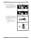
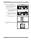
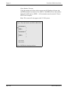
20. Locate the NT1 power cable. Plug cable into
power strip at bottom of cabinet and feed cable
through cable slot in rear of second shelf. Plug
second end of power cable into power input at rear
of the NT1.
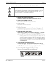
STEP ACTION DRAWING
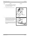
Polyethylene
Bag
Foam Inserts
Packing Carton
1
2
3
45
ON
1234
5
ON
POWER
U
NT1 REAR
POWER
HEADSET
POWER
LINE
B1 B2
NT1
VisuaLink 128/384
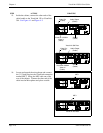
(one for 128)
(three for 384)
1
2
3
45
ON
POWER
U
Power Connection