


NDA-24230 Issue 2.0 Page 4-3
VisuaLink 128/384 User Guide Chapter 4
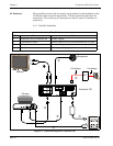
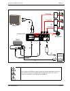
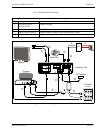
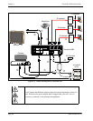
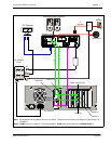
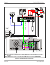
Figure 4-2: Connection Diagram for VisuaLink 384
➅
➆
➃
➂
①
➄
AC
VisuaLink 384
Camera
Monitor
➁
AC
+
+
+
+
+
DC IN 5V
+
-
Serial1 Serial2/RMT
O
U
T
I
N
VIDEO2 VIDEO1 AUDIO
++
TEL S/T LINE 1 S/T LINE 2 S/T LINE 3
MIC1 MIC2 MIC3
NT1
NT1
NT1
Microphone
S Interface
S Interface
S Interface
U Interface
An AC adapter has different output voltage and current depending on how it is
used. Please use the power adapter that is shipped with your unit. Also, if
incorrectly connected, it may damage the equipment.