


Page 4-10 NDA-24230 Issue 2.0
Chapter 4 VisuaLink 128/384 User Guide
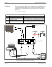
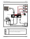
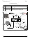
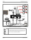
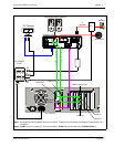
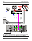
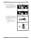
Figure 4-6: Connection Diagram for VisuaLink 384
NT1
+
+
+ +
+
DC IN 5V
+
-
Serial1 Serial2/RMT
O
U
T
I
N
VIDEO2 V IDEO1 AUDIO
++
TEL S/T LIN E 1 S/T LI NE 2 S/T LINE 3
MIC1 MIC2 MIC 3
AC
AC
VisuaLink 384
AC POWER
STRIP
Microphone
PC Terminal
PC Camera
AC
Video Capture Card
RS-232C
(COM1)
U
Interface
S
Interface
AC
V
i
d
e
o
O
u
t
A
u
d
i
o
O
u
t
Video InAudio In
Amplified Speakers (Optional)
NT1
NT1
COM Port 2
VIDEO DC IN 6V
COM Port 1
VGA Port
Note 1:
PC backpanel may be different than the one shown. Reference the PC manual and Capture card for location of
connectors.
Note 2:
COM 2 of the PC is used for T.120 communication. COM 1 should connect to the VL SERIAL PORT 1.