


Installation and configuration 69
Nortel Integrated Conference Bridge Service Implementation Guide
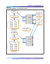
In the procedures that follow, the connections are the same for the
Option 11C and the CS 1000, the only difference is that the connectors
are on the back of the Call Server and Media Gateway for the CS 1000,
whereas they are on the bottom of the Option 11C cabinet.
Table 13 describes the DB-9 pin assignment that the next two
procedures use.
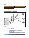
Procedure 8
Access the ICB directly – Option 11C or CS 1000
1 Position the Maintenance terminal on a desk near the system.
2 If the system is an Option 11C perform the following:
a Verify that the Ethernet Adapter is installed in the Option 11C.
b Plug the terminal cable DB-9 female connector into the DB-9 male
connector on the Ethernet Adapter on the I/O panel.
c Plug the DB-25 male connector at the other end of the terminal cable into
the RS-232 connector on the terminal. If the connection requires a
gender changer, obtain one at a local electronics store.
3 If your system is a CS 1000, connect the NTBK48 three-port SDI cable to the
9-pin SDI connection (COM RS-232) at the back of the Call Server and Media
This procedure is now complete
Gateway.
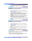
Procedure 9
Access the ICB remotely using a modem – Option 11C or CS 1000
1 Verify that the Ethernet Adapter/Medium Access Unit (MAU) is installed in the
Option 11C or CS 1000. Insert the industry-standard MAU into the Ethernet
Connection on the back of the Call Server and Media Gateway.
Note: The Ethernet MAU comes with the cable kits for the Call Server and Media
Gateway.
2 Plug the terminal cable DB-9 female connector into the DB-9 male connector
on the Ethernet Adapter/MAU on the I/O panel.
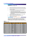
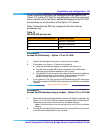
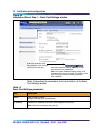
Table 13
DB-9 RS-232 port pin out
9-pin (male) serial connector pin # Signal Description
2 RS-232 TX (transmit)
3 RS-232 RX (receive)
5 GND