


9-22
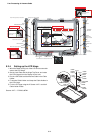
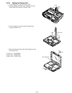
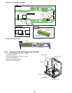
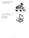
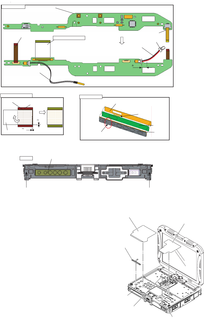
n Assembly of the Pad PCB and SW PCB
n Putting of the TP Bottom Tape
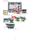
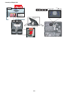
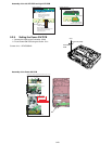
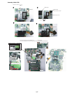
9.2.8. Setting the left LED PCB and right LED PCB
1. Connect the Cable to the Connector. (CN806)
2. Fix the left LED PCB.
3. Connect the Cable to the Connector. (CN801)
4. Fix the right LED PCB.
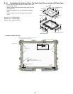
5. Attach the two Release Papers.
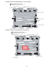
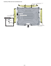
6. Attach the Palm Rest Ass'y.
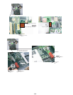
SW PCB Ass’y
Match the edge
and attach it.
Avoid coming off of the LED part,
or running over the LED part.
No direction when inserting
(Note) Arrow without specified measurement: 0 to 0.5 mm
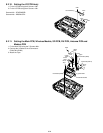
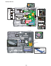
PAD PWB
SW FPC
LED(R) FPC
Power SW Cable
Operation
Sheet
Operation Tape
Power Cable Cushion
Thermistor
SW PCB
Ensure that the direction
is right when attaching.
The Connector bracket is
on the back side.
Insert
Insert
Insert
Insert
8 2mm
Back side
Wrap around the Cable.
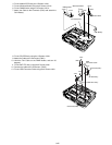
PAD PWB ASSY
PAD MAIN FPC ASSY
PAD MAIN FPC Ass’y
0 1mm
0 1mm
PAD-Main FPC
Tape
Stiffening Plate Side
Fold back
Front side
SW PCB Ass’y
Screw
Screw
Match to the upper left corner. 0 to 0.5mm
Release Paper
Release Paper
left LED PCB
right LED PCB
Connector(CN801)
Connector(CN806)