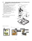
9-15
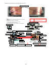
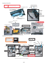
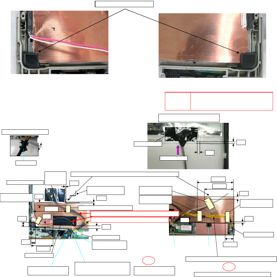
Assembly of LCD Unit(Only the model who doesn't have T/S)
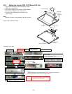
LCD drop holder Insert
0~1
0~2
5~7
7~9
6~8
41~43
2~4
0±1
59~61
0~1
16~18
2~4
3~5
4~6
62~63
4~6
71~73
0~1
CAUTION
S1:Insulation S2:Bitten S3:Sharp Edge
S4:Part No. Check S5:Other
1. Apply the load when attaching the attaching parts. 20 to 30N (2 to
<Notes>
3Kgf)/cm2
2. Reusing the attaching parts is impossible.
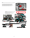
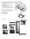
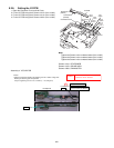
Fix with Screws in order of the rear number of No.
Ex.) Fix in order of Screw-1 to Screw-2.
Connect the LCD Cable.
Put the side of the socket pin up
and insert it into the CN of LCD.
Screw Set
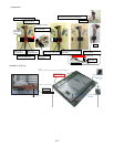
NEW GPS
Sheet
Attach.
Tape-2 Attach.
Top Case
Sheet-5 Attach.
Top Case
Sheet-1 Attach.
Tape-1 Attach.
Top Case
Sheet-4 Attach.
Top Case
Sheet-3 Attach.
Top Case Sheet-2 Attach.
Do not allow the tape to run over the LCD reflection plate.
Opalescent Screws
outer shape line
Confirm the Cable is separated(3 mm or more).
Confirm the sub material tape is wrapped.
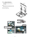
Fix the Connector..
Insert the CN.
Insert the CN.
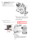
Set LCD cable Bush
into the rib firmly.
Process the Cable from the
inverter to the bottom side.
Process the LCD Cable on it.
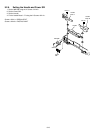
Avoid catching of
the INV Cable.
Avoid catching the
Cable in the Cabinet
Screw-2
Tighten
Screw-1
Tighten
LCD cable
BUSH Set
Ensure the Cable does not run over the inverter.
Avoid catching the Cable in the Cabinet
Avoid catching.
S2
S2
Torque of tightening Screw :0.45 ± 0.02N·m(Ṑ4.5 ± 0.2kgf·cm)


