


9-21
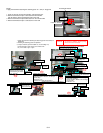
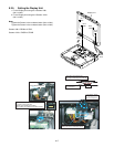
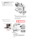
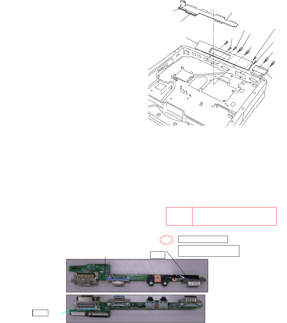
9.2.8. Setting the I/O PCB
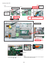
1. Open the Connector Cover and Lid Cover.
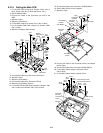
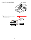
2. Fix the I/O PCB using the 3 Screws <N15> (No1 to No3).
3. Fix the I/O PCB using the 4 Screws <N14> (No1 to No4).
4. Fix the I/O PCB using the 2 Screws <N30> (No1 to No2).
Note:
Tighten the Screws in the numbered order (No1 to No3).
Tighten the Screws in the numbered order (No1 to No4).
Tighten the Screws in the numbered order (No1 to No2).
Screws <N14>: DFHE5058ZB
Screws <N15>; DRHM5104ZA
Screws <N30>; DXHM0057ZA
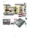
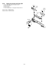
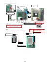
Assembly of I/O SUB PCB
Connector
(CN701)
Connector
(CN700)
I/O PCB
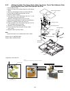
LID
Cover
Connector Cover
<N15>
No.3
<N15>
No.1
<N14>
No.1
<N14>
No.3
<N14>
No.4
<N30>
No.1
<N14>
No.2
<N15>
No.2
<N30>
No.2
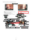
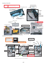
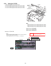
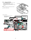
S1
CAUTION
S1:Insulation S2:Bitten S3:Sharp Edge
S4:Part No. Check S5:Other
Paste
Tighten
Reusing the attaching parts is impossible
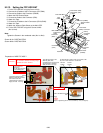
<Notes>
1.Apply the load when attaching the attaching parts. 20䱊30䰚䯴2䱊3Kgf䯵/cm2
Less than 0.5mm of difference
Insulation with a chassis
Substrate end face adjustment
Torque of tightening screw :0.19 ± 0.02N·m(Ṑ1.9 ± 0.2kgf·cm)
Screw
IO PCB Sheet
I/O㩷SUB PCB