


9-30
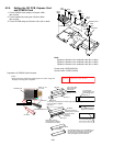
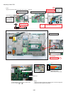
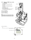
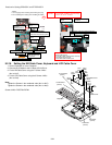
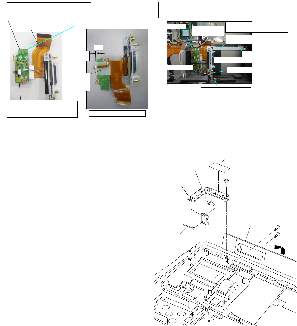
9.2.13. Setting the USB PCB and Antenna PCB
1. Open the Connector Cover.
2. Fix the Antenna PCB using the 2 Screws <N3>
(No1 to No2).
3. Connect the Black Cable.
4. Fix the USB PCB using the Screws <N6>.
5. Connect the Cable to the Connector (CN100).
6. Attach the Tape.
Note:
Tighten the Screws in the numbered order (No1 to No2).
Screws <N3>: DRQT2+G6FKL
Screws <N6>: DRQT26+E4FKL
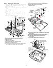
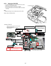
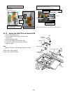
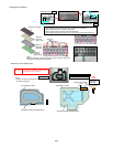
FPC ASSY #VVCEJ
ANT SW PCB #VVCEJ
Insert FPC into ANT SW PCB.
Match the FPC and the hole on the board.
Insert the plug.
Insert position: Match the stiffening
plate and board edge.
Lock it after FFC is inserted.
Match to the
edge of land.
0~1
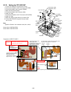
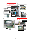
Overlap the board and the FPC, and set on the top Cabinet.
Insert the FPC into the main PCB.
Connect the coaxial Cable from Docking PCB.
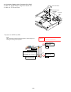
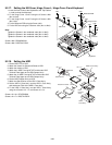
Screw-1 Tighten
Screw-2 Tighten
Screw-1 Tighten
Screw-2 Tighten
Fit to the arrow direction
and fix with Screw.
FRAME GUIDE
ANGLE ASM Attach
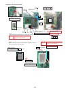
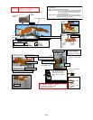
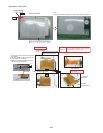
Lock after inserting FFC.
Ensure that FPC is not bended.
Screw-3 Tighten
Insert the FPC
into the socket.
LCD
Protection
Sheet
Attach.
Torque of tightening Screw :0.45 ± 0.05N·m(Ṑ4.5 ± 0.5kgf·cm)
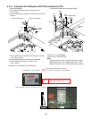
<N3>
<N3>
No.1
No.2
<N6>
USB PCB
Connector
(CN100)
Antenna PCB
Connector Cover
Antenna Cable
(Black)
Tape