


Connecting
Before connecting
Before connecting, carefully read the operating instructions for the external device to be connected. f
Turn off the power switch of the devices before connecting cables. f
Take note of the following points before connecting the cables. Failure to do so may result in malfunctions. f
- When connecting a cable to a device connected to the projector or the projector itself, touch any nearby metallic objects to
eliminate static electricity from your body before performing work.
- Do not use unnecessarily long cables to connect to a device connected to the projector or to the projector body. The longer
the cable, the more it is susceptible to noise. Since using a cable while it is wound makes it act like an antenna, it is more
susceptible to noise.
- When connecting cables, connect GND rst, then insert the connecting terminal of the connecting device in a straight
manner.
If any connection cable is not supplied with the device, or if no optional cable is available for connection of the device, f
prepare a necessary system connection cable to suit the device.
Video signals containing too much jitter may cause the images on the screen to randomly wobble or wafture. In this case, a f
time base corrector (TBC) must be connected.
The projector accepts VIDEO signals, S-VIDEO signals, YC f BCR/YPBPR signals and analog RGB signals (synchronous
signals are TTL level), and digital signal.
Some computer models are not compatible with the projector. f
When using long cables to connect with each of equipment to the projector, there is a possibility that the image will not be f
output correctly unless a compensator is used.
For details on what video signals the projector supports, see “List of compatible signals”. ( f Æ pages 130 -131)
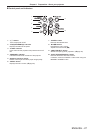
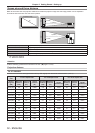
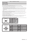
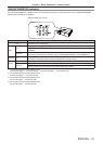
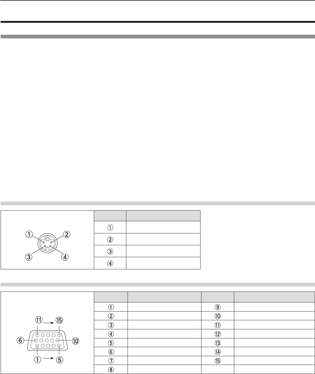
<S-VIDEO IN> terminal pin assignments and signal names
Outside view
Pin No. Signal names
GND (luminance signal)
GND (color signal)
Luminance signal
Color signal
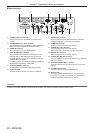
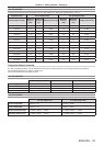
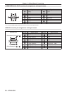
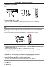
<COMPUTER 1 IN> terminal pin assignments and signal names
Outside view
Pin No. Signal names Pin No. Signal names
R/P
R
+ 5 V
G/Y
GND
B/P
B
GND
— DDC data
GND HD/SYNC
GND VD
GND DDC clock
GND
ENGLISH
-
35
Chapter 2 Getting Started - Connecting