


COMSPHERE 392xPlus Modems
1-4 November 1996 3920-A2-GN31-30
Model 3921
Plus
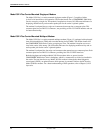
Carrier-Mounted Singleport Modem
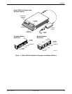
The
Model 3921
Plus
is a
carrier-mounted singleport modem (Figure 1-2) capable of either
4-wire/2-wire leased-line or dial operation. The modem installs into a COMSPHERE 3000 Series
Carrier, occupying a single slot. The modem’s faceplate has sixteen (16) LED status indicators for
displaying modem activity and an audio speaker jack for the carrier’
s optional speaker
.
The modem’
s back panel has two edge card connectors that mount into a connector plate. This
connector plate has two DB-25-S connectors, one providing an EIA-232-D DTE interface and one
for future functionality.
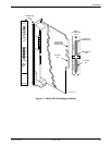
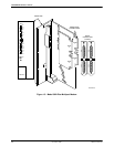
Model 3921
Plus
Carrier-Mounted Multiport Modem
The
Model 3921
Plus is a carrier-mounted multiport modem (Figure 1-3) equipped with an integral
time division multiplexer (TDM) with a modem sharing device (MSD). The modem installs into
the COMSPHERE 3000 Series Carrier, occupying two slots. The modem’
s faceplate covers two
slots in the carrier. It has twenty (20) LED status indicators for displaying modem activity and an
audio speaker jack for the carrier’
s optional speaker
.
The modem’s back panel has four edge card connectors that mount into two connector plates. Each
connector plate has two DB-25-S connectors providing four EIA-232-DTE interfaces.
Both the singleport and multiport Model 3921Plus modems derive ac power from the
COMSPHERE 3000 Series Carrier’
s backplane, which is a common bus to all devices installed in
the carrier. The user interface to any Model 3921Plus
modem is through the shared diagnostic
control panel (SDCP), an optional feature which operates in a manner similar to the DCP on the
Model 3920
Plus
modems
. For a better understanding of DCP operation, refer to Chapter 3, DCP
Operation.