


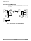
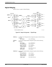
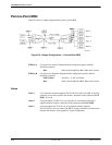
Sample Configurations
G-113920-A2-GN31-30 November 1996
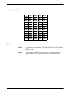
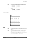
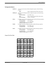
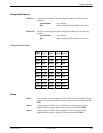
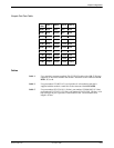
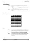
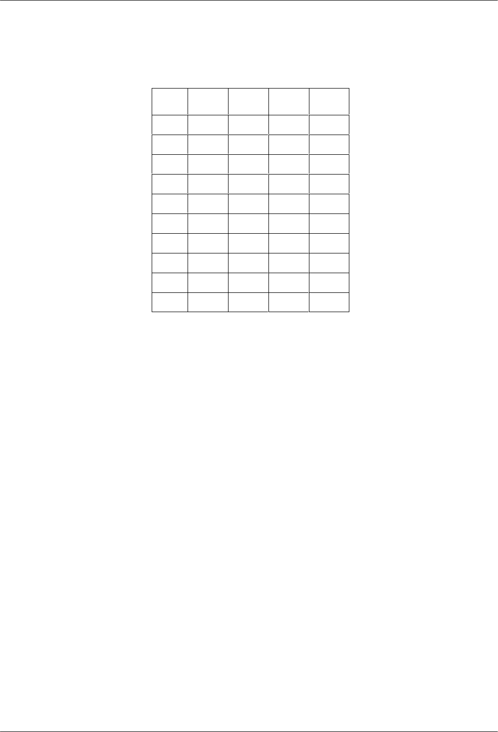
Sample Port Rate Table
Port
Rate
Port
1
Port 2 Port 3 Port 4
28.8K 9600 9600 4800 4800
24.0K 9600 Disable 4800 4800
19.2K 9600 Disable 4800 4800
16.8K 9600 Disable Disable 4800
14.4K 9600 Disable Disable 4800
12.0K Disable Disable Disable 4800
9.6K Disable Disable Disable 4800
7.2K Disable Disable Disable 4800
4.8K Disable Disable Disable 4800
2.4K Disable Disable Disable Disable
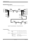
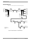
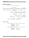
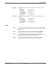
Cables
Cable 1 Use
a standard, customer
-supplied, EIA-232-D/V.24 cable with a DB-25-P (plug)
connector at one end to attach to the modem. Attach this to the connector labeled
DTE1, 2, 3, or 4.
Cable 2 Use part number 125-0053-1431 (an 8-position, 8-wire modular cord that is
supplied with the modem). Attach this to the connector labeled LEASED.
Cable 5 Use part number 835-1224-1011 (10 feet), part number 125-0040-0031 (12 feet),
part number 835-1224-2511 (25 feet), part number 835-1224-5011 (50 feet), or an
equivalent pin-to-pin, 6-position, 6-wire modular cord. The maximum cable
length is 50 feet.