COMSPHERE 392xPlus Modems
4-38 November 1996 3920-A2-GN31-30
Table 4-7
(6 of 8)
DTE Interface Configuration Options — Singleport Mode A
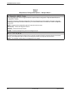
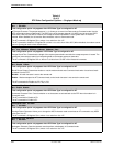
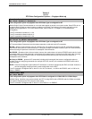
LSD Control: Stndrd_RS232
Nxt Stndrd_RS232 Forced_On WinkWhenDisc Follows_DTR Sim_Cntl_Car =DTR/DiscOFF
Line Signal Detect Control. LSD is a signal indicating that the carrier signal is being received from the remote modem. It
is normally turned OFF to the DTE when the power level of the received carrier signal drops below the carrier detect
threshold.
Standard RS232 – LSD is ON when the modem detects the remote modem’s carrier signal. LSD turns OFF when the
carrier signal strength drops below carrier detect threshold.
Forced On – Forces LSD to be ON at all times.
Wink When Disconnect – LSD is normally forced ON, but can be turned OFF for 1 to 2 seconds upon a disconnect.
This is used for UNIXr DTEs.
Follows DTR – The state of LSD follows the state of DTR. When DTR turns ON, LSD turns ON. When DTR turns OFF,
LSD turns OFF.
Simulated Control Carrier – LSD follows the state of RTS of the remote DTE via the V.13 simulated control carrier
signaling. This is required for hosts that cannot support full-duplex operation. If LSD Control is set to simulated control
carrier, then the RTS Action configuration option on the remote modem must be set to Simulated Control Carrier.
=DTR/Disconnect OFF – The state of LSD follows the state of DTR except when disconnecting once a connection is
established. In this instance, DTR remains ON and LSD turns OFF. DTR must then toggle OFF and then ON again for
LSD to turn ON. This setting is required for AT&T DATAKIT dial-out applications.
NOTE: If LSD Control is set to =DTR/DiscOff, then the DTR Action configuration option must be set to Stndrd_RS232.
The AT command for Forced On is &C0.
The AT command for Standard RS232 is &C1.
The AT command for Wink When Disconnect is &C2.
The AT command for Follows DTR is &C3.
The AT command for Simulated Control Carrier is &C4.
The AT command for =DTR/Disconnect OFF is &C5.
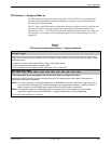
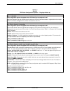
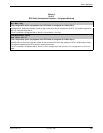
Tx Clock Source: Internal
Nxt Internal External RXC_Loop
This configuration option only appears when Async/Sync Mode is configured for Sync.
Transmit Clock Source. Determines the source of timing for synchronous data transmitted from the modem to the
analog channel.
Internal – The transmit data’s clock source is derived from the modem’s internal clock. This clock is available as an
output on Pin 15 (TXC) of the EIA-232-D interface.
External – The transmit data’s clock source is provided by the DTE on Pin 24 (XTXC) on the EIA-232-D interface.
Receive Clock Loop
– The modem’
s transmit clock is derived from its received analog signal. The derived clock is
available as an output on Pin 15 (TXC) of the EIA-232-D interface.
The AT command for Internal is &X0.
The AT command for External is &X1.
The AT command for RXC Loop is &X2.


