


Modem Installation
2-33920-A2-GN31-30 November 1996
Model 3920
Plus
Modem Installation
Before
installing your standalone modem, make sure your installation site is clean and
well-ventilated. Allow space around the modem for installing cables and telephone cords, and
make sure the modem is located within reach of the ac power outlet. The distance between your
modem and DTE should be minimized if DTE data rates exceed 19,200 bps. Also, low capacitance
cables may be necessary for speeds greater than 19,200 bps or distances greater than 50 feet.
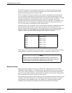
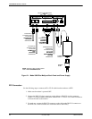
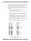
The back panel of the Model 3920Plus modem (Figure 2-1) has the following switches and
connectors:
• An ON/OFF power switch.
• An 8-pin DIN type power receptacle (PWR) for the dc power supply.
• An 8-pin modular keyed jack (LEASED) for 4-wire/2-wire leased lines.
• An 8-pin modular keyed jack (DIAL) for backup lines (2-wire dial or 2-wire leased).
• A 4-pin modular jack (NMS) for the Network Management System connection.
• One (singleport) or four (multiport) 25-pin DB-25-S receptacles for the DTE interfaces.
Connecting Cables to the Model 3920
Plus
Modem
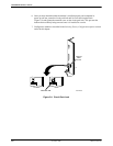
Instructions for connecting cables to the TELCO jack types using the appropriate cables apply to
both singleport and multiport Model 3920Plus modems. Figure 2-1 illustrates the Model 3920Plus
multiport modem. For pin assignments, refer to Appendix C.