


12 C2904M-B (2/05)
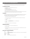
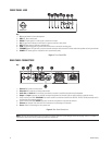
FRONT PANEL LEDS
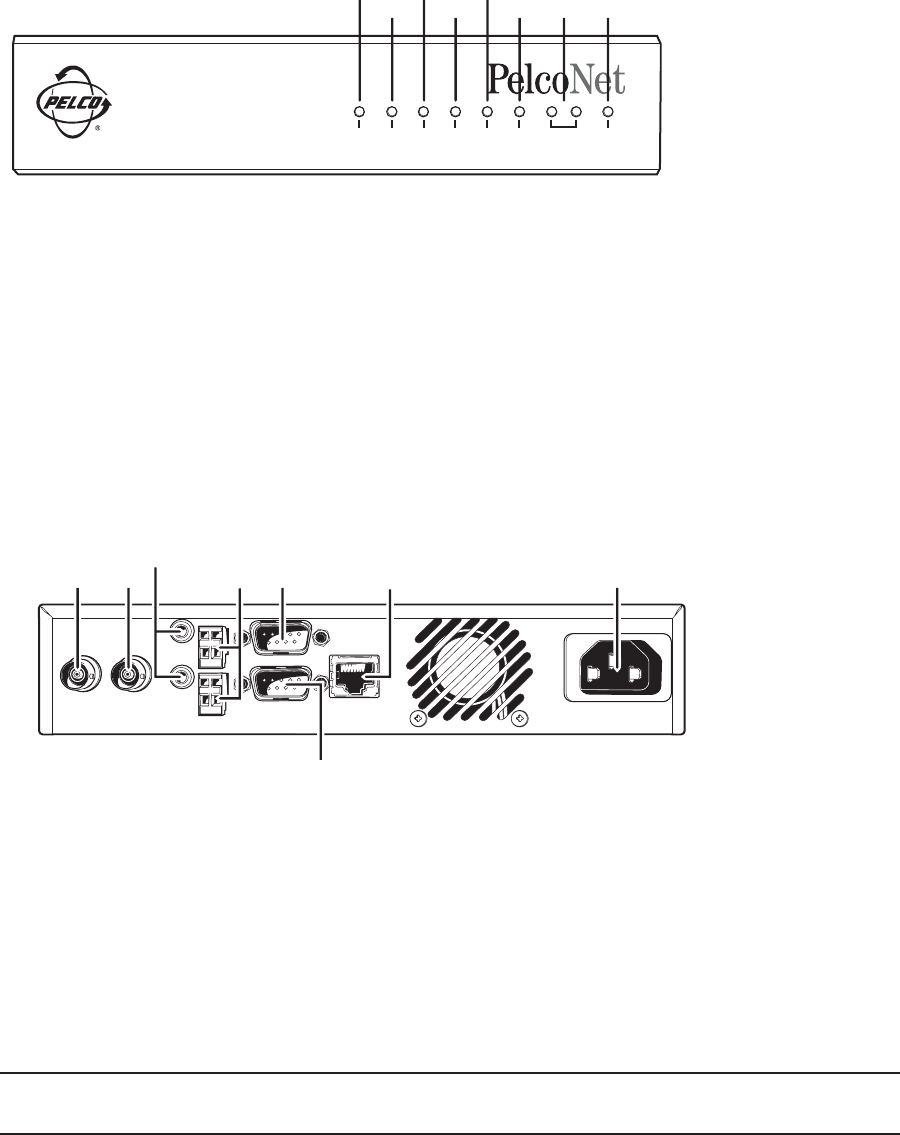
Video In Video Out
Audio In
10/100 Base-T
100-250VAC50/60Hz 100mA
COM2: RS232
ᕡ ᕢ ᕦ ᕨ
ᕣ
ᕤ
Ethernet
Audio Out
Power
ᕧ
COM1: RS232/485
ᕥ
Key:
1=IR (infrared) diode for future development.
2=HDD LED. Not currently used.
3=VIDEO LED lights green if a video signal is present on the input.
4=IN LED lights red to indicate an active alarm or green to indicate a ready alarm.
5=OUT LED lights green to indicate a switched relay.
6=COM LED flashes orange during active data transmissions on the serial interface ports.
7=ETHERNET green LED lights with a physical network connection while the red LED flashes when data packets are being transmitted.
8=POWER LED flashes green to indicate the unit is operationally ready.
Figure 1. Front Panel LEDs
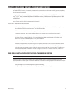
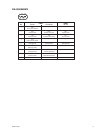
REAR PANEL CONNECTORS
Key:
1=Video In BNC socket for video source.
2=Video Out BNC socket for an analog video monitor.
3=Audio Out and Audio In 3.5 mm stereo jack sockets to connect an amplified microphone and loudspeaker.
4=Output and Input connectors for switches for external equipment (for example, lights or audible alarms) or external sensors.
5=Serial interface port COM 1 RS232/485 9-pin sub-D socket for control data transmissions (RS-232, RS-422, RS-485 protocols) and for
configuration using terminal software.
6=Serial interface port COM 2 RS232 9-pin sub-D socket for configuration using terminal software.
7=Ethernet port accepts Cat5 cable with RJ-45 connectors for connecting to the network.
8=Power socket for connecting the unit’s power cord.
Figure 2. Rear Panel Connectors
NOTE: Use only the supplied power plug. If the cable or connector show any sign of damage, do not use the plug. Send it in for repair or
replacement. Never try to use any power plug except the supplied one.
IR HDD VIDEO IN OUT COM ETHERNET POWER
MPEG 2/4 Network Video Codec
NET4001A
ᕡ
ᕢ
ᕣ
ᕤ
ᕥ
ᕦ ᕧ ᕨ