68 C2904M-B (2/05)
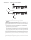
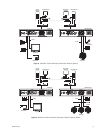
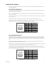
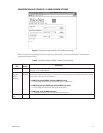
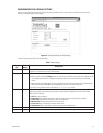
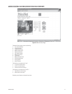
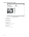
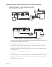
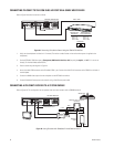
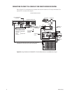
CONNECTING PELCONET TO THE COM IN RS-422 PORT ON A GENEX MULTIPLEXER
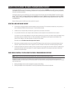
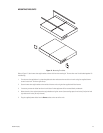
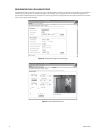
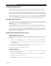
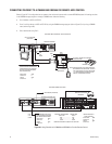
Refer to Figure 48 and the instructions to follow.
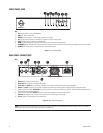
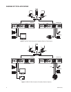
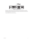
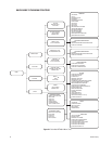
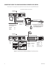
Figure 48. Connecting PelcoNet to Genex Using the COM IN RS-422 Port
1. Verify that the multiplexer has Version 4.1 firmware. (The version number flashes on the monitor when power is applied to the
multiplexer.)
2. Set the NET4001A COM1 data port to Transparent, 9600 baud, 8 data bits, odd (for parity), 1 stop bit, and off if it is not so set
already. (For Interface Mode select RS232.)
3. Create a cable using the diagram in Figure 44.
4. Attach the cable’s DB9 connector end to PelcoNet’s COM 1 port. Connect the cable’s RJ-45 connector end to COM IN on the back of
the multiplexer.
5. Connect the MAIN video output from the multiplexer to the NET4001A transmitter.
6. Connect PelcoNet’s Ethernet port to the network using a Cat5 Ethernet patch cable.
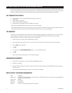
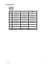
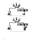
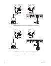
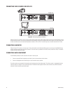
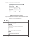
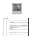
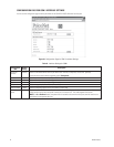
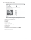
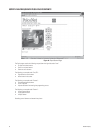
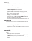
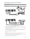
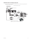
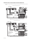
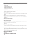
CONNECTING A PELCONET RECEIVER TO A SYSTEM CM9502
Refer to Figure 49. This configuration lets an operator view and control cameras with a CM9505 keyboard.
Video In Video Out
Audio Out
Audio In
COM1: RS232/485 10/100 Base-T
Ethernet
Power
100-250VAC50/60Hz 100mA
COM2: RS232
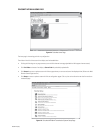
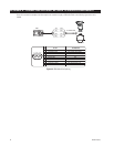
PELCONET TRANSMITTER
9600, 8, ODD, 1
PELCONET DB9
CONNECTOR
GENEX COM OUT
RJ-45 CONNECTOR
PIN 2
PIN 3
PIN 5
RX
TX
GND
PIN 6
PIN 4
PIN 5
TX
RX
GND
18
GENEX COM
TO NETWORK
18
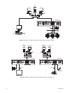
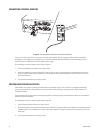
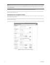
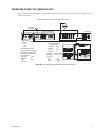
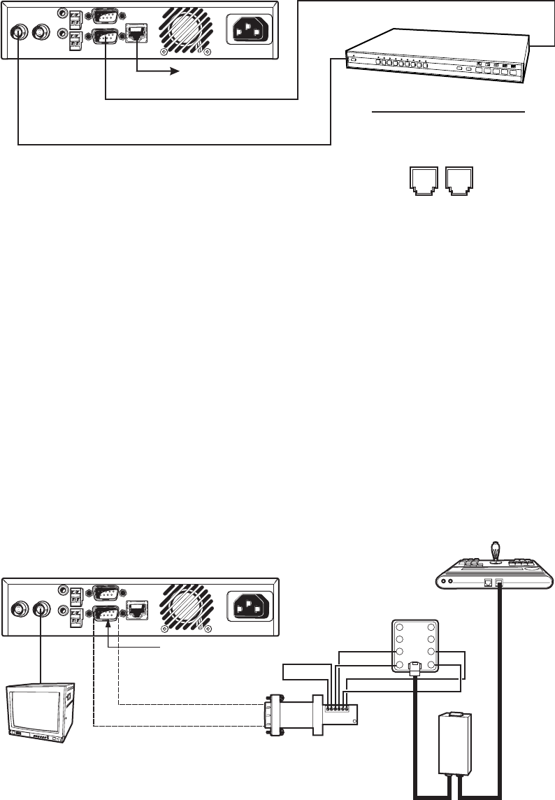
Figure 49. Using PelcoNet with CM9505 to Provide Remote Control
Video In Video Out
Audio Out
Audio In
COM1: RS232/485 10/100 Base-T
Ethernet
Power
100-250VAC50/60Hz 100mA
COM2: RS232
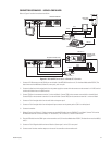
PELCONET RECEIVER
PV130
TD(A)
TD(B)
RD(A)
RD(B)
GND
+12 VDC
1
2
3
4
8
7
6
5
12 VDC
RD(A)
RD(B)
STRAIGHT
CABLE
KBD
CARD
CAGE
TD(A)
TD(B)
CM9505UPS
1200 BAUD, 8 BIT, 1 STOP BIT,
NO PARITY
CM9502-KBD
TRANSPARENT DATA