


26 C2904M-B (2/05)
CONNECTING EXTERNAL SENSORS
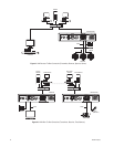
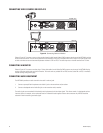
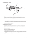
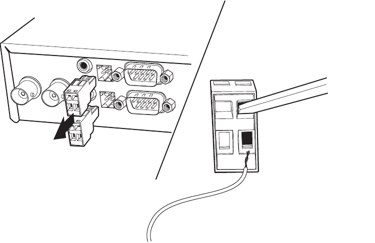
Figure 21. Connecting External Sensors and Peripheral Devices
The unit has an alarm input that lets you connect an external signaling device, like a door contact or motion detector. If configured
accordingly, an alarm trigger can, for example, set up an automatic connection between NET4001A and the remote station. You can
connect switches or contacts directly without a separate power supply.
Do the following to connect an external sensor. Refer to Figure 21.
1. Pull the Input (bottom) terminal block from its plug-in base.
2. Attach the conductor to the alarm input terminal. Either terminal will work. A ground conductor can be attached to the remaining
terminal if needed. (Insert a small screwdriver tip in the top square hole and push hard enough to open the lower hole. Insert the
wire in the lower hole.)
3. Push the terminal block back on to the plug-in base.
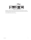
CONTROLLING PERIPHERAL DEVICES
The NET4001A has an output for switching an external device (for example, a light or siren). The relay can be operated interactively,
during an active connection, or automatically to coincide with certain events. Settings for the relay must be configured (refer to the
Configuration
section).
Typical applications of the relay output are activating door openers or switching of lights and other electrical devices. Do not exceed the
maximum rating of 40V and 0.8A.
Do the following to connect a peripheral device. Refer to Figure 21.
1. Pull the Output (top) terminal block from its plug-in base.
2. Attach the conductor to the output terminal. Either terminal will work. A ground conductor can be attached to the remaining terminal
if needed. (Insert a small screwdriver tip in the top square hole and push hard enough to open the lower hole. Insert the wire in the
lower hole.)
3. Push the terminal block back on to the plug-in base.