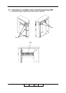
Preparation for Installation 4-17
II L 00
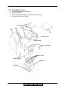
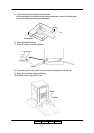
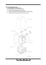
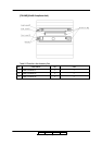
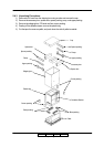
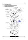
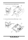
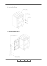
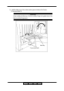
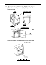
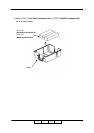
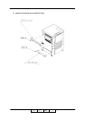
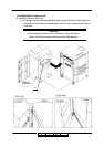
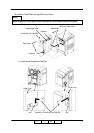
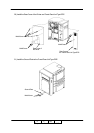
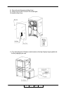
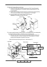
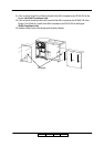
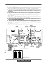
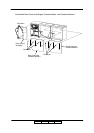
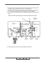
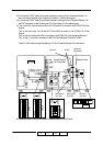
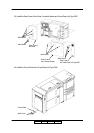
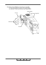
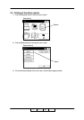
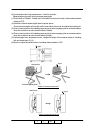
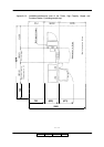
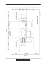
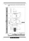
19) Connect the connector of cables to the Printer and Transit Pass Unit Type DDP.
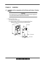
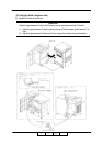
(1) Pass the three cables through the Hole of Printer and Transit Pass Unit Type DDP from
Transit Pass Unit Type DDP to Printer.
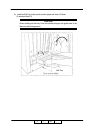
- AC cable (white 2pin connector) x2
- Signal cable (black 20pin (small) / black 14pin connector / black 22pin)
- GND cable
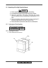
(2) Pass the one cable through the Hole of Printer and Transit Pass Unit Type DDP from Printer
to Transit Pass Unit Type DDP.
- FNS IF cable (white 4pin / black 20pin connector)
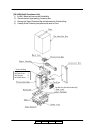
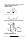
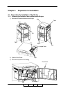
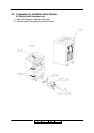
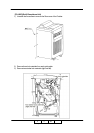
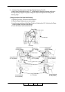
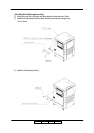
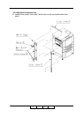
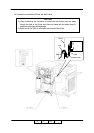
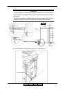
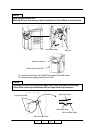
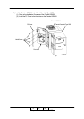
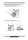
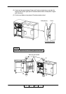
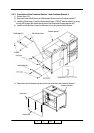
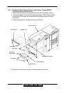
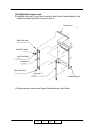
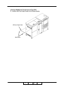
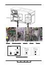
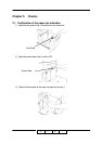
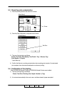
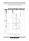
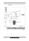
(3) Remove OCxxx PK.
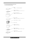
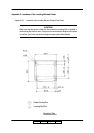
(4) Connect the Signal Cable to the connector on the CP board as follows.
(Connection 1)
- black 20pin connector (small size ) -> J747 (another side is not be connected)
- black 22pin connector -> between J717 and the original cable
- black 14pin connector -> J791(another side is not be connected)
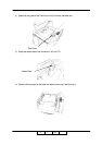
(5) Attach the OCxxx PK.
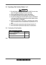
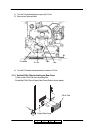
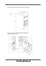
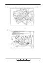
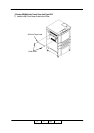
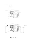
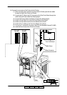
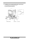
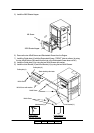
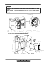
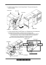
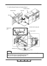
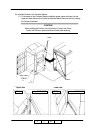
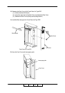
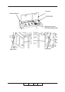
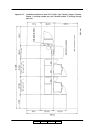
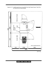
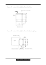
(6) Discinnect the CE AC cable from J236 on the Low Voltage Power Supply of Printer.
Connect the AC cable to the J236 on the Low Voltage Power Supply of Printer.
And connect the CE AC cable that is disconnected from J236 to the white 2pin connector of
the AC cable.
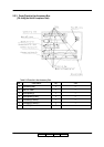
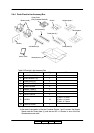
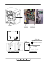
(Connection 2)
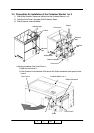
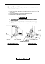
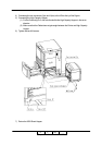
(7) Mount the FG cable on Printer frame by using M4 screw.
(Connection 3)
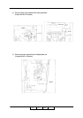
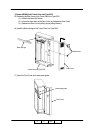
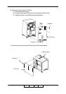
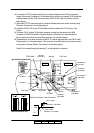
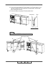
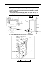
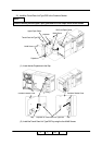
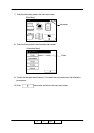
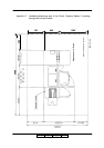
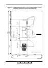
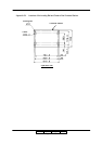
(8) Connect the FNS IF cable to the white 4pin connector in the Transit Pass Unit Type DDP.
(Connection 4)
(9) Connect the FNS IF cable to the black 20pin (plug type with lock) connector in the Transit
Pass Unit Type DDP.
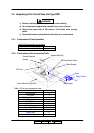
(Connection 5)
(10) Switch on No.8 of SW1 on the CP board of the Printer.
(11) Switch on No.6 of SW2 on the CP board of the Printer.
Note 1) Signal Cable (CS) in the Transit Pass Unit Type DDP is not used.
02