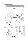
Preparation for Installation 4-30
II L 00
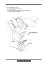
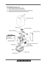
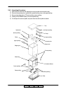
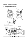
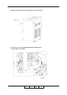
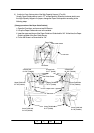
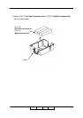
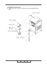
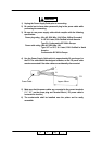
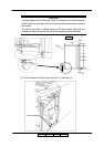
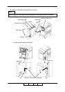
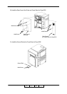
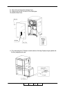
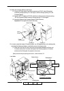
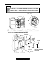
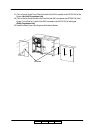
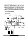
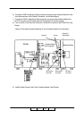
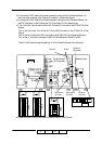
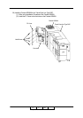
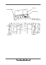
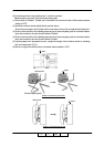
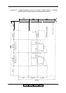
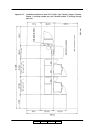
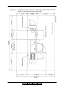
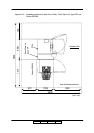
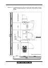
16) Connect the CST AC cable coming from the Container Stacker to the J236 on the power
supply of the printer (Connection 1 on the below figure). At this time, connect CE AC cable that
is disconnected from the J236 to the connector of the CST AC cable (Connection 2 on the
below figure)
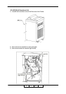
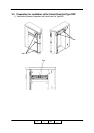
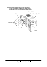
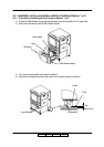
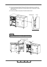
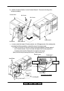
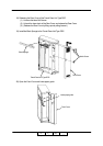
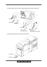
17) Mount the CST FG cable coming from Container Stacker side on the printer frame by using
M4 screw (Connection 3 on the below figure).
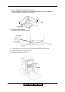
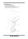
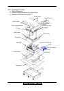
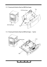
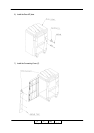
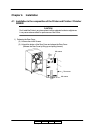
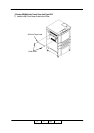
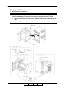
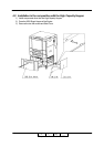
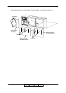
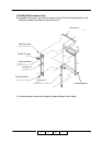
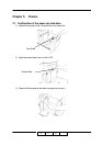
18) Install the CPXXX P/K on the CP P/K holder, and then install it with OC P/K ass’y in the
Engine.
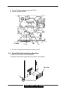
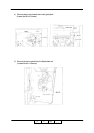
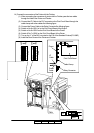
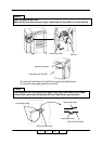
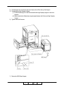
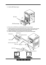
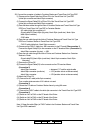
19) Connect FNS IF cable of 20 pin black connector coming from the printer to the J680
connector of ST09X P/K board in Container Stacker (Connection 4 on the below figure).
(Do not use the 4 pin white connector Disconnection 2 on the below figure).
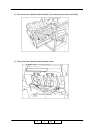
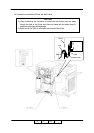
20) Disconnect the 4 pin white connector of the DC IF cable of the printer from the FNS IF cable
(Disconnection 1 on the below figure). Then connect it to the RB cable of 4 pin white connector
coming from Container Stacker. (Connection 5 on the below figure)
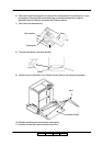
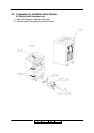
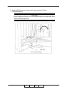
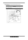
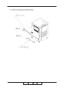
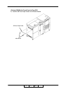
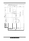
[Note] Put the cable through the opening “A” of the Engine for connection.
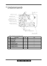
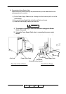
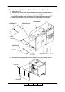
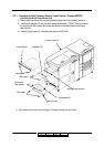
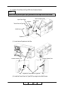
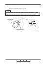
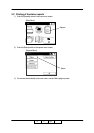
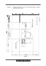
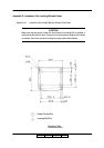
Details of Connection 1 and Connection2.
CTS AC cable
CE AC cable
Opening “A”
PS
DC IF cable
RB cable
FNS IF cable
M4 screw
(Connection 3)
Engine Container
CST FG cable
Connection 1
Connection 2
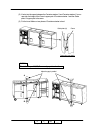
Connection 4
(20 pin black)
Disconnection 2
Connection 5
Disconnection 1
(4 pin white)
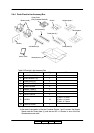
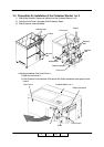
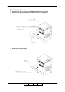
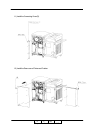
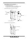
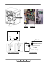
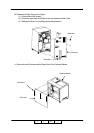
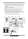
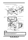
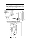
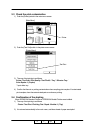
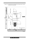
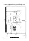
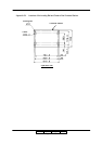
Disconnection 3
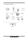
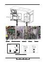
Connector : 2 pin white
Connector : 2 pin white
II L 01
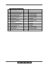
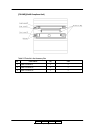
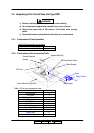
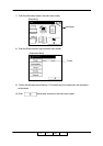
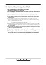
[RoHS Compliance Unit]
[No RoHS Compliance Unit]