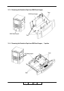
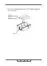
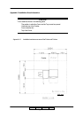
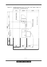
Preparation for Installation 4-35
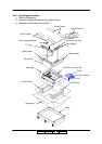
II L 00
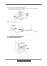
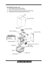
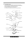
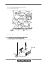
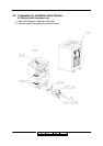
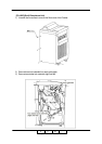
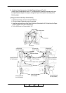
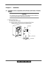
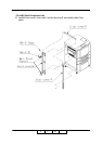
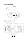
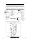
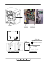
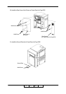
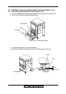
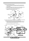
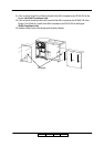
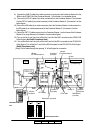
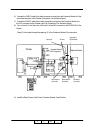
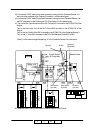
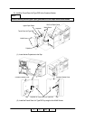
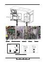
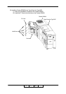
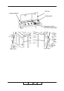
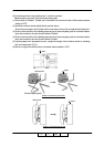
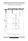
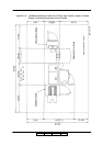
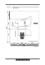
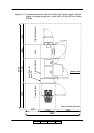
8) Connect the FNS IF cable (4 pin white connector) coming from the Container Stacker 2 to the
J680 on the ST09X P/K of the Container Stacker 1. (Connection 1 on the below figure)
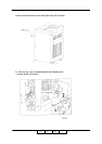
9) Take out the CST AC cable (2 pin white connector) from the Container Stacker 1 and connect
it to the CST AC cable (2 pin white connector) of the Container Stacker 2. (Connection 2 on the
below figure)
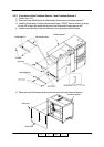
10) Take out the RB cable (4 pin white connector) from the Container Stacker 1 and connect it to
the RB cable (4 pin white translucence) of the Container Stacker 2. (Connection 3 on the
below figure)
11) Mount the CST FG cable coming from the Container Stacker 1 on the frame of the Container
Stacker 2 by using M4 screw (Connection 4 on the below figure).
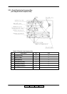
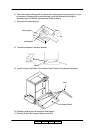
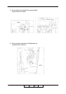
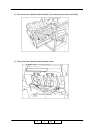
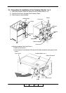
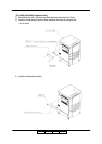
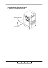
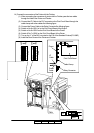
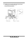
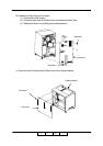
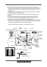
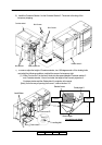
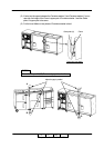
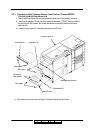
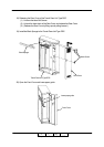
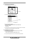
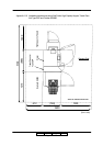
12) Turn on the No. 4 and 5 and turn off the No. 2 and 8 of the SW1 mounted on the CPXXX P/K
of the Engine. (No RoHS Compliance Unit)
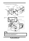
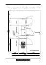
13) Turn on the No.4 and 5 and turn off the No.2 and 8 of the SW1 mounted on the CPXXX P/K
of the Engine. Turn off the No.7 and 8 of the SW2 mounted on the CPXXX P/K of the Engine.
(RoHS Compliance Unit)
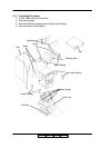
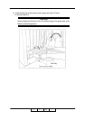
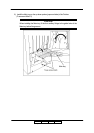
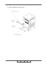
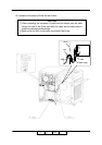
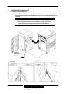
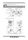
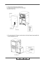
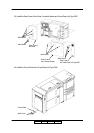
[Note] Put the cable through the opening “A” of the Engine for connection.
14)
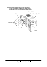
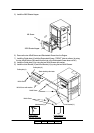
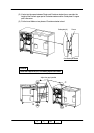
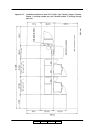
Connection 2
(2 pin white)
Connection 1
(20 pin black)
AF cable
(For Container Stacker 2)
(For Container Stacker 1)
Connection 3
(4 pin white)
CST AC cable
CST FG cable
M4 screw
Connection 4
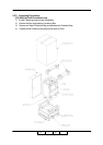
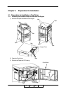
Engine
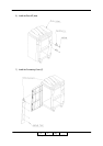
Container Stacker
2
(W/ Sample tray)
(W/ Through path)
Opening “A”
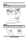
Container Stacker 1
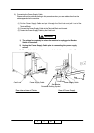
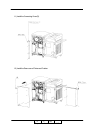
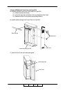
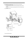
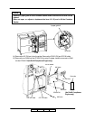
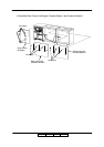
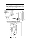
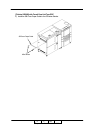
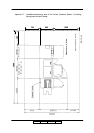
Disconnection 1(4 pin white)
Disconnection 2
(2 pin white)
II L 01
No RoHS Compliance
Unit
RoHS Compliance Unit