


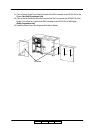
Preparation for Installation 4-27
II L 00
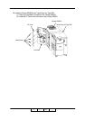
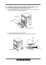
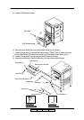
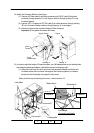
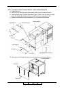
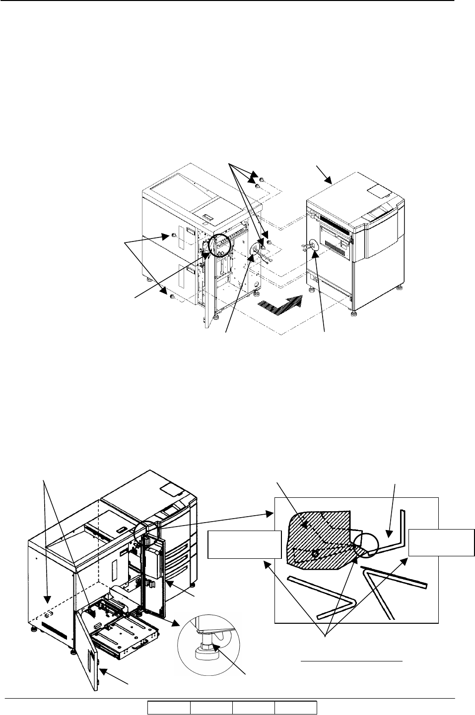
12) Attach the Container Stacker to the Engine.
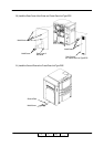
(1) Pass the AC Relay cable (2-pin white connector) and FNS IF cable (20-pin black
connector) through opening “A” in the Engine, and then through opening “B” in the
Container Stacker.
(2) Pass the CST FG cable and CST AC cable (2-pin white connector) through opening
“B” in the Container Stacker, and then through opening “A” in the engine.
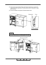
(3) Attach the Engine to the Container Stacker (6 M4x12 screws).
Important: Do not tighten the screws all the way.
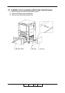
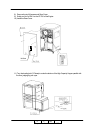
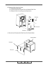
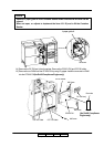
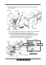
13) In order to adjust the height of Container stacker, turn 180 degrees each of four leveling bolts,
and satisfy the following conditions, and bolt the screw of a temporary tight.
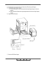
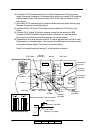
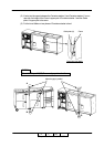
(1) When the Front cover R is shut and it looks into the space between the Printer and
Container stacker from front side, the height of the Frame’s projection of Container
stacker and the Guide plate U’s projection is the same.
[Note] As for the way of opening front cover L, refer to the item 3.3.
Level Meter
Leveling bolts
Front cover L
Guide plate U
Stacker frame
Same height
Connection part Details
Projection
Projection
Front cover R
M4x12
Screws
M4x12 Screws
Frame
projection part
Engine
Opening
”
B
”
Opening ”A”
II L 01