


100
ENGLISH
Configurable I/O Application Functions
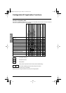
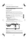
Recommended settings for brake control, for a vertical lifting application :
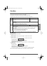
1Brake release frequency (brL) :
Set the brake release frequency to the value of the nominal slip multiplied by the nominal frequency in Hz
(g x FS).
Calculation method :
Ns = synchronous speed in rpm.
(for 50 Hz supply : Ns = 3000 rpm for a motor with 1 pair of poles, 1500 rpm for a motor with 2 pairs of poles,
1000 rpm for a motor with 3 pairs of poles and 750 rpm for a motor with 4 pairs of poles,
for 60 Hz supply : Ns = 3600 rpm for a motor with 1 pair of poles, 1800 rpm for a motor with 2 pairs of poles,
1200 rpm for a motor with 3 pairs of poles and 900 rpm for a motor with 4 pairs of poles).
- Nr = nominal speed at nominal torque in rpm, use the speed indicated on the motor rating plate.
Release frequency = g x Fs.
- g = slip calculated previously
- Fs = nominal motor frequency (indicated on the motor rating plate)
Example : for a motor with 2 pairs of poles, 1430 rpm given on plate, 50 Hz supply.
g = (1500 - 1430) / 1500 = 0.0466
Brake release frequency = 0.0466 x 50 = 2.4 Hz
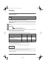
2Brake release current (Ibr) :
Adjust the brake release current to the nominal current indicated on the motor.
Note regarding points 1 and 2 : the values indicated (release current and release frequency) correspond to
theoretical values. If during testing, the torque is insufficient using these theoretical values, retain the brake
release current at the nominal motor current and lower the brake release frequency (up to 2/3 of the nominal
slip). If the result is still not satisfactory, return to the theoretical values then increase the brake release
current (the maximum value is imposed by the speed controller) and increase the brake release frequency
gradually.
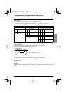
3 Acceleration time :
For lifting applications, it is advisable to set the acceleration ramps to more than 0.5 seconds. Ensure that
the speed controller does not exceed the current limit.
The same recommendation applies for deceleration.
Note : for a lifting movement, a braking resistor should be used. Ensure that the settings and configurations
selected cannot cause a drop or a loss of control of the lifted load.
4Brake release delay (brt) :
Adjust according to the type of brake. It is the time required for the mechanical brake to open.
5Brake engage frequency (bEn) :
Set to twice the nominal slip (in our example 2 x 2.4 = 4.8 Hz). Then adjust according to the result.
6Brake engage delay (bEt) :
Adjust according to the type of brake. It is the time required for the mechanical brake to close.
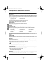
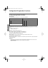
Loss of 4-20 mA signal
(APL), can be assigned to R2 or L0
The logic output is set to 1 if the signal on the 4-20 mA input is less than 2 mA.
slip
Ns Nr–()
Ns
-------------------------=
GP_ATV58_EN.fm Page 100 Mardi, 2. avril 2002 6:09 18