


147
C:\WINNT\Profiles\Administrator\Desktop\WORK_08_21\370467401
DVS9000WW\01GB04C02-WW.fm
masterpage:Right
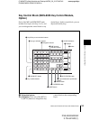
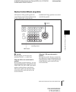
Names and Functions of Parts of the Control Panel
Chapter 2 Menus and Control Panel
DVS-9000/9000SF
3-704-674-01 (1)
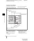
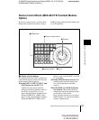
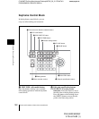
Device Control Block (MKS-8031TB Trackball Module,
Option)
The device control block is used for three-
dimensional transform operations using a
DME, for wipe pattern position setting, and
for VTR operation.
a Region selection buttons
The operation mode allocated to the device
control block depends on the selection state
of the region selection buttons.
When the [M/E 1], [M/E 2], [M/E 3], and
[P/P] buttons are selected: This
enables the wipe pattern position
setting (positioner) operation mode in
the device control block. You can
select multiple buttons simultaneously.
When the MKS-9011 1M/E Control
Panel is used, only the [P/P] is enabled.
When the MKS-9012 2M/E Control
Panel is used, only the [M/E-1] and [P/
P] are enabled.
When the [USER] button is selected: This
enables pattern position setting used
for color backgrounds and frame
memory.
When the [DME 1] to [DME 8] buttons
are selected: This enables the three-
dimensional transform operation mode
in the device control block.
Press a button, turning it on, to select a
DME channel. You can select multiple
buttons simultaneously.
DEVUSER
M/E1
DME1
DME5
MENU
SHIFT
M/E2
DME2
DME6
ASP
PERS
SUB
LOC
SIZE
FMR1
AXIS
LOC
MAIN
LOCAL
K1
CB1
GLB
K2
CB2
CLR
WORK
BUFR
M/E3
DME3
DME7
SRC
K3
FM1
TRGT
K4
FM2
LOC
XYZ
FMR2
X
P/P
DME4
DME8
ROT
POS
Y Z CTR
RUN
CTRL
1 Region selection buttons
3 Trackball
4 Z-ring
2 Operating buttons
5 MENU button