


Chapter 2 Menus and Control Panel
C:\WINNT\Profiles\Administrator\Desktop\WORK_08_21\370467401
DVS9000WW\01GB04C02-WW.fm
masterpage:Left
148
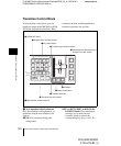
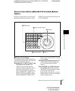
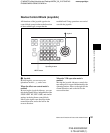
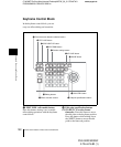
Names and Functions of Parts of the Control Panel
DVS-9000/9000SF
3-704-674-01 (1)
The number of valid buttons depends
on the number of DME processor
channels installed.
Note
In the DVS-9000 system, DME5 to
DME8 are not available.
When the [DEV] button is selected: This
enables the VTR operation mode in the
device control block. In this state, the
[M/E 1] and [M/E 2] buttons function
as the device 1 and device 2 allocation
buttons.
To exit from this mode, press the
[DEV] button again, turning it off.
When the [RUN CTRL] button is
selected: This enables the effect run
control mode in the device control
block.
The functions of the operation buttons,
trackball, and Z-ring vary with the
operation mode as follows.
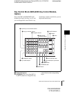
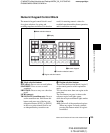
b Operation buttons
When the positioner operation mode is
enabled
K1 CB1: Press this button to enable wipe
pattern position setting for key 1
(DSK1).
When the [USER] button is selected,
pattern position setting for color
background 1 is enabled.
K2 CB2: Press this button to enable wipe
pattern position setting for key 2
(DSK2).
When the [USER] button is selected,
pattern position setting is enabled for
color background 2.
K3 FM1: Press this button to enable wipe
pattern position setting for key 3
(DSK3).
When the [USER] button is selected,
pattern position setting is enabled for
frame memory 1.
K4 FM2: Press this button to enable wipe
pattern position setting for key 4
(DSK4).
When the [USER] button is selected,
pattern position setting is enabled for
frame memory 2.
MAIN: Press this button to enable main
wipe pattern position setting for normal
transitions.
SUB: Press this button to enable sub wipe
pattern position setting for normal
transitions.
Among the [K1 CB1] button, [K2 CB2]
button, [K3 FM1] button, [K4 FM2] button,
[MAIN] button, and [SUB] button, you can
make a multiple selection.
POS: Press this button to enable pattern
movement in the x-axis and y-axis
directions with the trackball.
When the [USER] button is selected,
this enables the trackball to move the
pattern in the x-axis and y-axis
directions, and the Z-ring to adjust the
size of the pattern.
X, Y: These restrict the axes affected by the
trackball and Z-ring to the x- or y-axis.
They also allow entry of a numeric
value for the corresponding axis using
the numeric keypad control block.
Z: When the [USER] button is selected, this
restricts the axes affected by the
trackball and Z-ring to the z-axis. It
also allows entry of a numeric value for
the z-axis using the numeric keypad
control block.
CTR (center): When this button is pressed,
the pattern position returns to the
center. When the [USER] button is
selected, the pattern size also returns to
50.00.
SHIFT/CLR WORK BUFR: These are
not used in positioner operation mode.