


195
C:\WINNT\Profiles\Administrator\Desktop\WORK_08_21\370467401
DVS9000WW\01GB05C03-WW.fm
masterpage:Right
Executing a Transition
Chapter 3 Transitions
DVS-9000/9000SF
3-704-674-01 (1)
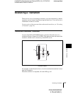
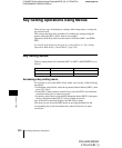
Fader Lever Operation in Bus Fixed Mode
In the bus fixed mode there is a fixed relationship between the position of the
fader lever and the signal output on each bus. Depending on the direction of the
transition, the fader lever must therefore always be moved in a particular
direction, as shown in the following table. This does not affect an auto
transition, which is executed regardless of the fader lever direction.
For an overview of the bus fixed mode, see “Flip-flop mode and bus fixed
mode” (page 33).
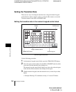
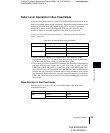
Fader lever operating direction in bus fixed mode
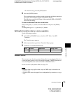
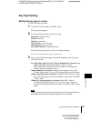
• When a transition applies to a combination of more than one of the
background and keys 1, 2, 3, and 4, then the transition for all of these must
be in the same direction complying with the above table.
• If as a result of an auto transition, for example, the fader lever position does
not agree with the signal output, this is a non-sync state (see page 194) and
LEDs light at both end positions of the fader lever travel. Moving the fader
lever does not carry out a transition, but when the fader lever reaches the end
position the non-sync state is released, and it is now possible to carry out the
next transition. If the fader lever is moved in the direction away from the lit
LEDs, this carries out the next transition, over the remaining part of the fader
lever travel.
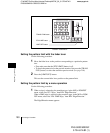
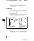
Wipe direction in bus fixed mode
The direction of a wipe is also in a fixed relationship to the fader lever
movement direction.
Next transition Transition direction Fader lever movement
Background A t BDownward
B t A Upward
Keys 1, 2, 3, and 4 On t Off (deletion) Downward
Off t On (insertion) Upward
Transition type Wipe direction Fader lever movement
Wipe Normal Upward
Reverse Downward